


Static charge-electricity detector
#static charge
#electricity detector
#ion emission
#high voltage
#static electricity
#electrostatic fields
#sensor
#measurement

Description: The detector is designed to sense static charges and free ions present in the air. It can indicate the presence of ion emissions, high voltage, static electricity, and electrostatic fields. The grounding can be achieved through an earth ground or by touching a metal object with the hand. The meter operates within a 100 µA range, and the R3 potentiometer is used to control the sensitivity of the detector.
The electronic schematic for this detector consists of several key components that work together to achieve its functionality. The core of the circuit includes a sensitive meter that operates on a 100 µA range, allowing it to detect minute currents associated with static charges and ion emissions. The meter is connected in series with a sensing element that can detect the presence of static electricity and free ions in the environment.
The sensing element is typically a field-effect transistor (FET) or a specialized ion sensor that responds to changes in electric fields. When static charges or free ions are present, they induce a voltage change across the sensing element, which is then translated into a current that drives the meter.
To enhance the performance of the detector, a potentiometer (R3) is included in the circuit. This component allows for the adjustment of the sensitivity of the detector, enabling it to be calibrated for different environments or applications. By varying the resistance of the potentiometer, the threshold at which the detector responds to static charges can be modified, making it adaptable to various levels of ion emissions or static electricity.
The grounding method is critical for the accurate operation of the detector. It can either be connected to an earth ground, providing a stable reference point, or it can utilize a metal object that can be touched by the user. This flexibility allows the circuit to function effectively in different settings, whether in a laboratory or an industrial environment.
Overall, the design of this static charge and ion detection circuit emphasizes sensitivity and adaptability, making it a valuable tool for measuring electrostatic fields and ensuring safety in environments where static electricity may pose a risk.The detector will sense static charges and free ions in the air. It can be used to indicate the presence of ion emission, high voltage, static electricity, and electrostatic fields. The ground can be an earth ground or a touching metal by your hand. The meter is 100uA range and R3 potentiometer is by controlling the sensitivity of the detector.
The electronic schematic for this detector consists of several key components that work together to achieve its functionality. The core of the circuit includes a sensitive meter that operates on a 100 µA range, allowing it to detect minute currents associated with static charges and ion emissions. The meter is connected in series with a sensing element that can detect the presence of static electricity and free ions in the environment.
The sensing element is typically a field-effect transistor (FET) or a specialized ion sensor that responds to changes in electric fields. When static charges or free ions are present, they induce a voltage change across the sensing element, which is then translated into a current that drives the meter.
To enhance the performance of the detector, a potentiometer (R3) is included in the circuit. This component allows for the adjustment of the sensitivity of the detector, enabling it to be calibrated for different environments or applications. By varying the resistance of the potentiometer, the threshold at which the detector responds to static charges can be modified, making it adaptable to various levels of ion emissions or static electricity.
The grounding method is critical for the accurate operation of the detector. It can either be connected to an earth ground, providing a stable reference point, or it can utilize a metal object that can be touched by the user. This flexibility allows the circuit to function effectively in different settings, whether in a laboratory or an industrial environment.
Overall, the design of this static charge and ion detection circuit emphasizes sensitivity and adaptability, making it a valuable tool for measuring electrostatic fields and ensuring safety in environments where static electricity may pose a risk.The detector will sense static charges and free ions in the air. It can be used to indicate the presence of ion emission, high voltage, static electricity, and electrostatic fields. The ground can be an earth ground or a touching metal by your hand. The meter is 100uA range and R3 potentiometer is by controlling the sensitivity of the detector.

Gate automatic lamp circuit
The circuit utilizes multiple integrated circuits to form an automatic lighting device that is activated by door and window sensors. It includes CD4093 digital integrated circuits, a relay, and a power supply circuit. The system typically remains closed when a...

Preregulated-high-voltage-supply
One of the control circuit's triacs selects the tap on the main transformer T1, which provides the proper preregulated voltage to the secondary regulator. T2 and its associated components comprise the secondary regulator. The ADC 0804, IC1, digitizes a voltage...
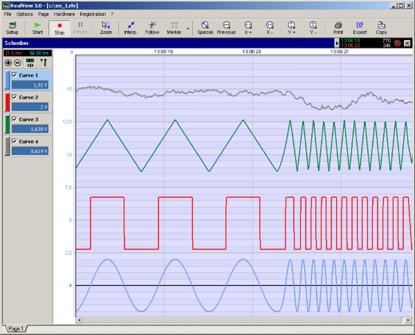
RealView 2.0
RealView is a measurement application, which records and plots measured values from analogue hardware devices in real-time. Several curves can be plotted into a single diagram. Several diagrams can be arranged on one or more pages if necessary. Plot options...

The 25-30kV DC Generator
This High Voltage power supply is able to generate up to 25-30kV DC Output from a 12-24v DC input. With a fully adjustable DC input power supply (0-24V/4A), it is possible to adjust the HV output between 5 to 30kV....

Foldback Current Limited High Voltage Regulator
This circuit is a high voltage regulator that features foldback current limiter protection. It utilizes the LM10 comparator along with a voltage reference in its core design.
The high voltage regulator circuit is designed to maintain a stable output voltage while...
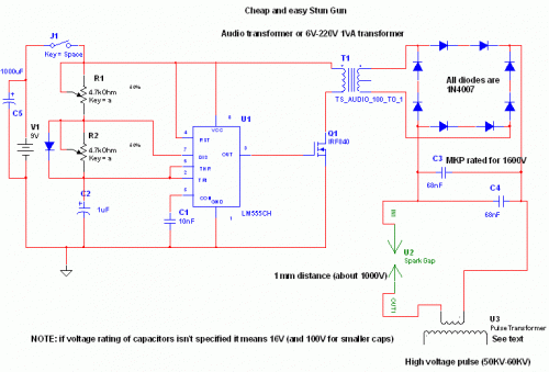
High Voltage Stun Gun
This device can be used against aggressive animals or attackers; however, it is important to note that it may be illegal in certain states.
The device in question is designed for personal protection and can serve as a deterrent against aggressive...

Nitrogen Laser High Voltage Power Supply
The schematic of the power supply is illustrated below. It operates using standard household power of 120VAC at a frequency of 50/60Hz, with an adjustable output that can reach up to 25kV or higher.
The power supply circuit is designed to...

High-voltage-bucking-regulator
This circuit is essentially a classic buck regulator that utilizes a TMOS N-channel power FET for the chopper and generates its own supply for gate control. The unique feature of this circuit is its method for creating a separate supply...

High Voltage High Current Power Supply
The circuit can produce about 250-500mA at 2KV, depending on the transformer. For C1, you can use the capacitor out of an old microwave. This circuit is mainly provided as a demonstration of using commonly available parts for something uncommon....