


Temperature and relative humidity meter using an inexpensive DHT11 sensor
#DHT11
#temperature sensor
#humidity sensor
#digital output
#calibrated
#inexpensive
#environmental monitoring
#microcontroller
#Arduino
#home automation

Description: The DHT11 is the most affordable sensor currently available in the market that provides calibrated digital outputs for temperature and relative humidity.
The DHT11 sensor is a low-cost digital sensor that measures both temperature and relative humidity. It operates on a single-wire protocol, allowing for a simple interface with microcontrollers such as Arduino or Raspberry Pi. The sensor typically provides temperature readings in degrees Celsius and humidity readings as a percentage.
Key specifications of the DHT11 include a temperature range of 0 to 50 degrees Celsius with an accuracy of ±2 degrees Celsius, and a humidity range of 20% to 80% with an accuracy of ±5% relative humidity. The sensor is powered by a 3 to 5V DC supply, making it suitable for various applications, including home automation systems, weather stations, and IoT devices.
In terms of integration, the DHT11 consists of a capacitive humidity sensor and a thermistor for measuring temperature. The data output is sent in a digital format, which simplifies the process of reading the values through a microcontroller's GPIO pin. The sensor requires a pull-up resistor connected to the data line to ensure proper signal integrity.
To utilize the DHT11 sensor in a circuit, it is essential to connect the VCC pin to a power source, the GND pin to ground, and the data pin to a digital input on the microcontroller. Additionally, appropriate libraries, such as the DHT library for Arduino, can be used to facilitate communication and data retrieval from the sensor.
Overall, the DHT11 sensor is a practical choice for projects requiring basic temperature and humidity monitoring due to its low cost and ease of use.DHT11 is the most inexpensive sensor currently available in the market that provides calibrated digital outputs for temperature and relative humidity. It is availab..
The DHT11 sensor is a low-cost digital sensor that measures both temperature and relative humidity. It operates on a single-wire protocol, allowing for a simple interface with microcontrollers such as Arduino or Raspberry Pi. The sensor typically provides temperature readings in degrees Celsius and humidity readings as a percentage.
Key specifications of the DHT11 include a temperature range of 0 to 50 degrees Celsius with an accuracy of ±2 degrees Celsius, and a humidity range of 20% to 80% with an accuracy of ±5% relative humidity. The sensor is powered by a 3 to 5V DC supply, making it suitable for various applications, including home automation systems, weather stations, and IoT devices.
In terms of integration, the DHT11 consists of a capacitive humidity sensor and a thermistor for measuring temperature. The data output is sent in a digital format, which simplifies the process of reading the values through a microcontroller's GPIO pin. The sensor requires a pull-up resistor connected to the data line to ensure proper signal integrity.
To utilize the DHT11 sensor in a circuit, it is essential to connect the VCC pin to a power source, the GND pin to ground, and the data pin to a digital input on the microcontroller. Additionally, appropriate libraries, such as the DHT library for Arduino, can be used to facilitate communication and data retrieval from the sensor.
Overall, the DHT11 sensor is a practical choice for projects requiring basic temperature and humidity monitoring due to its low cost and ease of use.DHT11 is the most inexpensive sensor currently available in the market that provides calibrated digital outputs for temperature and relative humidity. It is availab..

Ice warning and lights reminder circuit diagram project
This electronic project circuit diagram for an ice warning and lights reminder system alerts drivers when their vehicle lights should be activated and warns them if the outside temperature approaches zero degrees Celsius. The system employs an LED indicator and...

Hook Sensor Loop Circuit
An effective temperature sensor circuit is designed to receive power from a 4-to-20 mA loop without impacting the loop current. The temperature sensor integrated circuit (IC) used is the AD590F, which operates with a supply voltage ranging from 4 V...
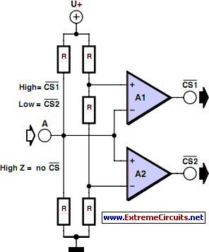
Multitasking Pins circuit
It is entirely logical that low-cost miniature microcontrollers have fewer pins than their larger counterparts, sometimes too few. Consideration has been given to how to economize on pins by making them perform the work of several. It was noted that...

Training Boxing timer schematic
A timer is being developed for circuit training or boxing training. The timer does not require any external input, except for a reset function. The project can be simplified using a microcontroller, such as the PIC12F635, which is cost-effective at...

Arduino LED Dimmer
The initial step involves selecting software, and CadSoft Eagle was chosen due to the abundance of available tutorials, making it a suitable starting point. Once the process is understood, the choice of software can be reconsidered. For now, the free...
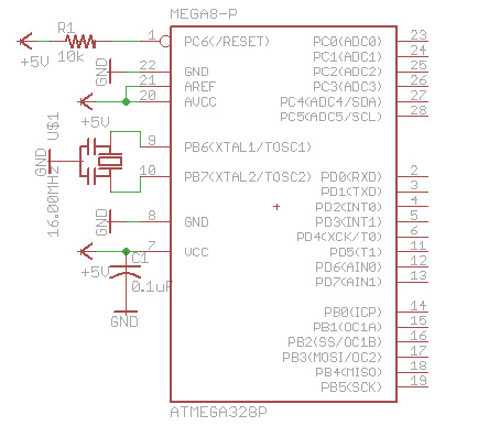
small bare bone arduino bluduino
There are many bare-bones Arduinos available on the internet. Most of them are assembled on a solderless breadboard and utilize an ATmega168 (or ATmega328) microcontroller with an Arduino bootloader, a resonator (which may have built-in capacitors or require two external...

Air humidity measuring circuit 2
The humidity alarm system is based on integrated circuits and relays, utilizing the pA741 circuit. The MS01 employs a wet-type humidity resistance element as a probe. When the humidity exceeds a predetermined value, specifically set at 6 feet high, relay...

thermometer circuit
When the system is placed in a shop or mall, logos and product advertisements serve as an ideal complement to temperature information. For home use, photographs of children at the beach or, should the temperature drop, images of making a...

The electronic thermometer circuit diagram for blind
Measuring range: room temperature is -10 to 40 degrees Celsius; body temperature is 36 to 41 degrees Celsius; Resolution: room temperature is 0.5 degrees Celsius, body temperature is 0.05 degrees Celsius; error: room temperature <1 degree Celsius, body temperature <0.1 degrees Celsius. When switch S1 is in position 1, it displays the room temperature profile; position 2 displays the body temperature profile. Components V1, R1, R2, RP1, and RP2 form the temperature measurement circuit.
The temperature measurement circuit is designed to monitor and display two distinct temperature ranges: ambient room temperature and body temperature. The circuit operates with a measuring range for room temperature from -10 to 40 degrees Celsius and for body temperature from 36 to 41 degrees Celsius. The resolution of the circuit is fine-tuned to provide accurate readings, with a room temperature resolution of 0.5 degrees Celsius and a body temperature resolution of 0.05 degrees Celsius. The specified error margins indicate a maximum deviation of less than 1 degree Celsius for room temperature measurements and less than 0.1 degrees Celsius for body temperature measurements.
The circuit utilizes a switch, S1, which allows the user to select between the two temperature profiles. In position 1, the circuit outputs the room temperature, while in position 2, it outputs the body temperature. The operational components include a voltage source (V1), resistors (R1, R2), and potentiometers (RP1, RP2) that are integral to the measurement process. Resistors R1 and R2 are likely part of a voltage divider network that aids in scaling the temperature sensor output to a readable format. Potentiometers RP1 and RP2 can be used for calibration purposes, allowing fine adjustments to ensure that the readings are accurate within the specified error margins.
The temperature sensor, which is not explicitly mentioned but is assumed to be part of the circuit, converts temperature changes into an electrical signal that can be processed by the circuit. The output from the sensor is conditioned by the resistive components to produce a voltage level that corresponds directly to the measured temperature. This voltage is then displayed on an appropriate display unit, which could be an analog gauge or a digital readout, depending on the design of the circuit.
Overall, this temperature measurement circuit is a practical solution for monitoring both ambient and body temperatures with high accuracy and user-friendly operation through the selection switch.