


Temperature controlled DC fan
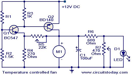
Description: This circuit utilizes two transistors to regulate the speed of a 12 V DC fan based on temperature changes. A thermistor (R1) detects the temperature. As the temperature rises, the base current of transistor Q1 (BC 547) increases, leading to a decrease in its collector voltage. This drop in collector voltage of Q1 is coupled to the base of transistor Q2 (BD 140), which enhances the forward bias on Q2, consequently increasing the fan speed. The brightness of an LED in the circuit is also correlated with the fan speed.
This circuit employs a thermistor as a temperature sensor, which is a resistor that changes its resistance with temperature variations. In this application, the thermistor (R1) is connected in such a way that its resistance decreases as the temperature increases. This change in resistance affects the base current flowing into Q1 (BC 547), a general-purpose NPN transistor.
When the temperature rises, the thermistor's resistance drops, allowing more current to flow into the base of Q1. This increased base current results in a higher collector current, which in turn lowers the collector-emitter voltage (Vce) of Q1. The collector of Q1 is connected to the base of Q2 (BD 140), a PNP transistor. As the collector voltage of Q1 decreases, it increases the forward bias on Q2, allowing it to conduct more current from its emitter to collector. This increased current through Q2 drives the 12 V DC fan at a higher speed.
The operation of the fan is directly proportional to the temperature, offering a simple yet effective way to control fan speed. Additionally, an LED can be included in the circuit to provide a visual indication of the fan speed. The brightness of the LED will vary in accordance with the fan speed, providing a simple feedback mechanism to the user. The circuit can be powered with a 12 V supply, and proper biasing resistors should be selected for both transistors to ensure they operate within their specified limits. Proper thermal management should also be considered, especially if the circuit is to be used continuously.Here is a simple circuit based on two transistors that can be used to control the speed of a 12 V DC fan depending on the temperature. A thermistor (R1) is used to sense the temperature. When the temperature increases the base current of Q1 (BC 547) increases which in turn decreases the collector voltage of the same transistor.
Since the collector of Q1 is coupled to the base of Q2 (BD 140), the decrease in collector voltage of Q1 forward biases the Q2 more and so do the speed of the motor. Also, the brightness of the LED will be proportional to the speed of the motor.
This circuit employs a thermistor as a temperature sensor, which is a resistor that changes its resistance with temperature variations. In this application, the thermistor (R1) is connected in such a way that its resistance decreases as the temperature increases. This change in resistance affects the base current flowing into Q1 (BC 547), a general-purpose NPN transistor.
When the temperature rises, the thermistor's resistance drops, allowing more current to flow into the base of Q1. This increased base current results in a higher collector current, which in turn lowers the collector-emitter voltage (Vce) of Q1. The collector of Q1 is connected to the base of Q2 (BD 140), a PNP transistor. As the collector voltage of Q1 decreases, it increases the forward bias on Q2, allowing it to conduct more current from its emitter to collector. This increased current through Q2 drives the 12 V DC fan at a higher speed.
The operation of the fan is directly proportional to the temperature, offering a simple yet effective way to control fan speed. Additionally, an LED can be included in the circuit to provide a visual indication of the fan speed. The brightness of the LED will vary in accordance with the fan speed, providing a simple feedback mechanism to the user. The circuit can be powered with a 12 V supply, and proper biasing resistors should be selected for both transistors to ensure they operate within their specified limits. Proper thermal management should also be considered, especially if the circuit is to be used continuously.Here is a simple circuit based on two transistors that can be used to control the speed of a 12 V DC fan depending on the temperature. A thermistor (R1) is used to sense the temperature. When the temperature increases the base current of Q1 (BC 547) increases which in turn decreases the collector voltage of the same transistor.
Since the collector of Q1 is coupled to the base of Q2 (BD 140), the decrease in collector voltage of Q1 forward biases the Q2 more and so do the speed of the motor. Also, the brightness of the LED will be proportional to the speed of the motor.

simple intercom circuit with
This is a two-station simple intercom circuit built using transistors and common 8-ohm mini speakers. The speaker functions as a microphone and generates sound, eliminating the need for a separate microphone in this intercom setup. The "press-to-talk" switches should have...

Simple Transistor Amplifier Circuit Schematic and Explanation
This circuit does not function as effectively as it could. It was created when the designer had a limited understanding of circuit design. An improved schematic will be developed and posted later, featuring a better design. The schematic indicates "antenna,"...

Eggs hatching incubator circuit diagram 4
The egg hatching incubator circuit comprises a power supply circuit, a constant temperature control circuit, and a sound and light alarm circuit, as illustrated in Figure 4-7. The power supply circuit includes a power switch (S1), a fuse (FU2), a...

100W full-wave single-junction transistor trigger doer control circuit
A 100W full-wave single-junction transistor trigger control circuit designed for constant or variable speed control of a wire feed motor. The input control signal consists of a voltage adjusted by the master potentiometer (RPs) and a feedback voltage from potentiometer...
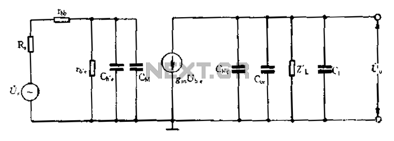
Common emitter amplifier circuit resistance and capacitance coupled basic
Common emitter amplifier circuit with resistance and capacitance coupling.
The common emitter amplifier circuit is a fundamental configuration in analog electronics, widely utilized for its ability to amplify voltage signals. This circuit employs a bipolar junction transistor (BJT) as the active...

Tickler oscillator circuit
When the circuit is initially powered, neither transistor is activated, resulting in high base voltages for both and a tendency to turn on. Due to slight asymmetries, one transistor will activate first, leading the circuit into one of its states...
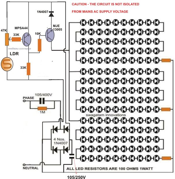
Electronics Projects: Simple 12 Volt Day Night Switch
At times, it is quite frustrating to see street lights remaining switched on even during broad daylight. The current circuit for an automatic night light can effectively address this issue. This article explains how to construct such a system. It...
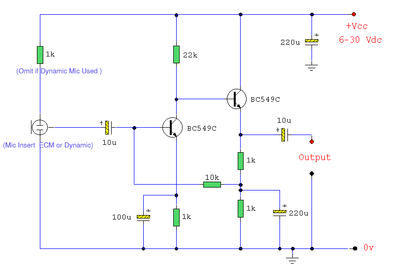
ECM Mic Preamplifier
Both transistors should be low noise types. In the original circuit, BC650C was used, which is an ultra-low noise device. These transistors are now hard to find, but BC549C or BC109C are good replacements. The circuit is self-biasing and will...

12V Car Battery Charger
This is a simple 12V car battery charger circuit designed to address common issues found in most car battery chargers. One major problem is that if the charger remains on, the battery can overcharge, potentially damaging the charger plates and...