


Three Axis Mag
#magnetometer
#3-axis
#magnetic field
#orientation sensing
#Earth's magnetic field
#sensor
#measurement
#vehicle detection

Description: The Micromag3 is a 3-axis magnetometer that measures the strength of magnetic fields in three directions. It can detect magnetic fields comparable to the Earth's magnetic field. Common applications include orientation sensing and detecting local disruptions in the Earth's magnetic field, such as those caused by vehicles. The Micromag3 is manufactured by PNI Corporation and is available for $50 on their website and for $55 at Sparkfun. A similar 2-axis magnetometer is available from PNI for $40-45, depending on whether it is purchased as a module or on a carrier board, and for $50 at Sparkfun. Magnetic fields are vector fields, meaning that measuring a magnetic field at a specific point reveals both its strength and direction. The Micromag3 can measure the strength of the magnetic field perpendicular to a single sensing element's orientation. By measuring magnetic field strength along three perpendicular axes, it can determine the strength and direction of the field in three-dimensional space. There are four primary scenarios in which interaction with magnetic fields is likely. First, the Earth possesses an inherent magnetic field. Measuring this field along two axes can provide north-south orientation, while measuring it along three axes, in conjunction with other sensors, can offer three-dimensional orientation. Second, large metal objects, such as cars, can disrupt the local strength and direction of the Earth's magnetic field. Changes in magnetic fields at a location can be utilized to detect the presence of such objects. Third, permanent magnets produce magnetic fields that are typically much stronger than the Earth's magnetic field. Similar to vehicle detection, a magnetometer may be used to track the position of a known magnet. Fourth, all electric currents generate magnetic fields perpendicular to the current's direction; conversely, a magnetic field can induce a current, which is the operational principle of the Micromag3. The Micromag3 measures magnetic fields through magnetoinductance. A detailed description of the circuit and sensor operation can be obtained from PNI, along with a 1998 article from Sensors magazine discussing various methods for sensing magnetic fields, including magnetoinductance. Additionally, a 1996 article from EDN compares several techniques for measuring magnetic fields. A magnetoinductive circuit comprises a coil around a ferromagnetic core, integrated into a circuit that forms a relaxation oscillator. Charge accumulates in the circuit, is rapidly discharged, and then begins to build up again, creating oscillation. The frequency of this oscillation varies with the strength of the magnetic field perpendicular to the coil. In the Micromag3, the generated oscillation is a square wave, easily interpreted as a digital signal. The Micromag3 determines magnetic field strength by comparing two measurements from the same circuit. Initially, one end of the circuit is grounded while the other oscillates. Then, the opposite end is grounded, and the first oscillates. The difference between these results provides temperature stabilization and indicates the direction of the magnetic field. One pin is selected, and the output is an oscillating square wave. The period of 256 cycles of this square wave is measured. To measure along one axis, pin 1 is selected and its period is measured, followed by pin 2, with the difference yielding the final result, which is expected to be linearly proportional to the magnetic field strength.
The Micromag3's operation relies on precise measurements of magnetic flux changes, which are processed through a dedicated microcontroller. The microcontroller facilitates the conversion of the oscillating square wave signal into meaningful data regarding magnetic field strength and direction. The device's compact design allows for integration into various applications, including robotics, navigation systems, and mobile devices. The sensor's ability to provide real-time data enhances its utility in dynamic environments where magnetic field variations occur. Furthermore, the integration of temperature compensation mechanisms ensures that the readings remain accurate across a range of operating conditions. The Micromag3's output can be interfaced with microcontrollers or other digital systems, enabling seamless integration into larger electronic systems. The versatility and precision of the Micromag3 make it a valuable component for developers and engineers working with magnetic field detection and orientation sensing.The Micromag3 is a 3-axis magnetometer that measures the strength of magnetic fields in 3 directions. It can measure magnetic fields that are approximately the same strength as the Earth`s magnetic field.
Common applications include orientation sensing and for sensing local disruptions in the Earth`s magnetic field, such as those caused by vehicle s. The datasheet summary can be found here. The Micromag3 is manufactured by PNI Corporation and is available through their website for $50. ( ) It is also available at Sparkfun for $55. There is a similar 2-axis magnetometer available for $40-45 from PNI (depending on whether you buy the module only or buy the module on a carrier board) and for $50 from Sparkfun. For starters, magnetic fields are vector fields ”that is, if you`re measuring a magnetic field at a given point, that field will have both a strength and a direction.
The Micromag3 can measure the strength of the magnetic field that`s perpendicular to the orientation of a single sensing element. Thus, by measuring magnetic field strength on three perpendicular axes, it is possible to measure the strength and direction of the field in three-dimensional space.
There are probably four main situations in which you are likely to interact with magnetic fields. One, the earth has an inherent magnetic field. Measuring that field on two axes can provide north-south orientation, and measuring that field on 3 axes, in combination with some other sensors, can provide three-dimensional orientation. Second, large metal objects (such as cars), can disturb the local strength and direction of the earth`s magnetic field.
Measuring changes in magnetic fields in a location can be used to detect the presence of such objects. Third, permanent magnets produce magnetic fields (usually much stronger than the earth`s magnetic field).
Similarly to detecting the presence of vehicles, there may be some possibilities for using a magnetometer to track the position of a known magnet. Fourth, all electric currents produce magnetic fields perpendicular to the direction of the current (and vice versa ”a magnetic field can be used to induce a current, which is how the Micromag3 works).
A circuit (such as a solenoid) can be designed to intentionally create a magnetic field, or the current in a circuit may produce noise that interferes with a magnetometer`s functioning. The Micromag3 measures magnetic field through magnetoinductance. A description of the circuit and how the sensor works can be downloaded from PNI here, and this 1998 article from Sensors magazine describes a variety of methods for sensing magnetic fields, including magnetoinductance.
This1996 article from EDN also compares several methods of measuring magnetic fields. A magnetoiductive circuit consists of a coil around a ferromagnetic core that is incorporated into a circuit that forms a relaxation oscillator. Charge gradually builds up in the circuit, is rapidly discharged, and then starts to gradually build up again, and so on.
The frequency of this oscillation varies with the strength of the magnetic field perpendicular to the coil. In the micromag3, the oscillation that is produced is a square wave, which can be easily read as a digital signal.
The Micromag3 calculates magnetic field strength by comparing two measurements from the same circuit. First one end of the circuit is grounded, and the other oscillates. Then the other end is grounded, and the first oscillates. Subtracting one result from the other provides temperature stabilization and (I think) the direction of the magnetic field.
One pin is selected, and the output is an oscillating square wave. The period of 256 cycles of the square wave is measured. To measure on one axis, first pin 1 is selected, and the period measured, then pin 2 is selected and the period measured, and their difference is the final result. This result should be linearly proportional to the magneti
The Micromag3's operation relies on precise measurements of magnetic flux changes, which are processed through a dedicated microcontroller. The microcontroller facilitates the conversion of the oscillating square wave signal into meaningful data regarding magnetic field strength and direction. The device's compact design allows for integration into various applications, including robotics, navigation systems, and mobile devices. The sensor's ability to provide real-time data enhances its utility in dynamic environments where magnetic field variations occur. Furthermore, the integration of temperature compensation mechanisms ensures that the readings remain accurate across a range of operating conditions. The Micromag3's output can be interfaced with microcontrollers or other digital systems, enabling seamless integration into larger electronic systems. The versatility and precision of the Micromag3 make it a valuable component for developers and engineers working with magnetic field detection and orientation sensing.The Micromag3 is a 3-axis magnetometer that measures the strength of magnetic fields in 3 directions. It can measure magnetic fields that are approximately the same strength as the Earth`s magnetic field.
Common applications include orientation sensing and for sensing local disruptions in the Earth`s magnetic field, such as those caused by vehicle s. The datasheet summary can be found here. The Micromag3 is manufactured by PNI Corporation and is available through their website for $50. ( ) It is also available at Sparkfun for $55. There is a similar 2-axis magnetometer available for $40-45 from PNI (depending on whether you buy the module only or buy the module on a carrier board) and for $50 from Sparkfun. For starters, magnetic fields are vector fields ”that is, if you`re measuring a magnetic field at a given point, that field will have both a strength and a direction.
The Micromag3 can measure the strength of the magnetic field that`s perpendicular to the orientation of a single sensing element. Thus, by measuring magnetic field strength on three perpendicular axes, it is possible to measure the strength and direction of the field in three-dimensional space.
There are probably four main situations in which you are likely to interact with magnetic fields. One, the earth has an inherent magnetic field. Measuring that field on two axes can provide north-south orientation, and measuring that field on 3 axes, in combination with some other sensors, can provide three-dimensional orientation. Second, large metal objects (such as cars), can disturb the local strength and direction of the earth`s magnetic field.
Measuring changes in magnetic fields in a location can be used to detect the presence of such objects. Third, permanent magnets produce magnetic fields (usually much stronger than the earth`s magnetic field).
Similarly to detecting the presence of vehicles, there may be some possibilities for using a magnetometer to track the position of a known magnet. Fourth, all electric currents produce magnetic fields perpendicular to the direction of the current (and vice versa ”a magnetic field can be used to induce a current, which is how the Micromag3 works).
A circuit (such as a solenoid) can be designed to intentionally create a magnetic field, or the current in a circuit may produce noise that interferes with a magnetometer`s functioning. The Micromag3 measures magnetic field through magnetoinductance. A description of the circuit and how the sensor works can be downloaded from PNI here, and this 1998 article from Sensors magazine describes a variety of methods for sensing magnetic fields, including magnetoinductance.
This1996 article from EDN also compares several methods of measuring magnetic fields. A magnetoiductive circuit consists of a coil around a ferromagnetic core that is incorporated into a circuit that forms a relaxation oscillator. Charge gradually builds up in the circuit, is rapidly discharged, and then starts to gradually build up again, and so on.
The frequency of this oscillation varies with the strength of the magnetic field perpendicular to the coil. In the micromag3, the oscillation that is produced is a square wave, which can be easily read as a digital signal.
The Micromag3 calculates magnetic field strength by comparing two measurements from the same circuit. First one end of the circuit is grounded, and the other oscillates. Then the other end is grounded, and the first oscillates. Subtracting one result from the other provides temperature stabilization and (I think) the direction of the magnetic field.
One pin is selected, and the output is an oscillating square wave. The period of 256 cycles of the square wave is measured. To measure on one axis, first pin 1 is selected, and the period measured, then pin 2 is selected and the period measured, and their difference is the final result. This result should be linearly proportional to the magneti

Wire Break Sensor Alarm Circuit Schematic
The circuit of a loop sensor-based simple security alarm is described here. The sensor loop consists of a short length of thin enamelled copper wire.
The loop sensor security alarm operates on the principle of detecting interruptions in the circuit formed...

Magnetic Field Sensor circuit
This DIY magnetic field sensor circuit is straightforward and capable of detecting both fixed magnetic fields and those that vary at audio frequencies. The device is not designed for precise measurement of magnetic field strength. A small and relatively weak...

B-Field Measurer
This circuit generates an output voltage that is proportional to the magnetic induction (B) detected by its probe's coil. The coil must be sized to produce a full-scale, 10-V output corresponding to the maximum expected intensity of magnetic induction. The...
RealView 2.0
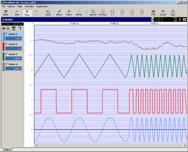
RealView is a measurement application, which records and plots measured values from analogue hardware devices in real-time. Several curves can be plotted into a single diagram. Several diagrams can be arranged on one or more pages if necessary. Plot options...

Sensor-Activated Relay Pulser Circuit
A sensor activates transistor Q1 to turn on the low-frequency 555 oscillator, which generates pulses to control LAMP II. The sensor may respond to variations in light or temperature. Either resistor RA or RB can function as the sensor, depending...

Gate automatic lamp circuit
The circuit utilizes multiple integrated circuits to form an automatic lighting device that is activated by door and window sensors. It includes CD4093 digital integrated circuits, a relay, and a power supply circuit. The system typically remains closed when a...

Add a sensor to a board and measure something with it
This week's plan is to build a device that warns of the potential for a knockdown, which is the process by which an over-canvassed ship is laid over on her beam-ends. The risk of sinking is high during this event,...

Blanket internal measurement circuit disconnection
The internal disconnection circuit for a blanket operates on the principle of induction. It includes a wire approximately 2 cm in length that senses the proximity of a charged mains power source. When the sensing wire is close to the...
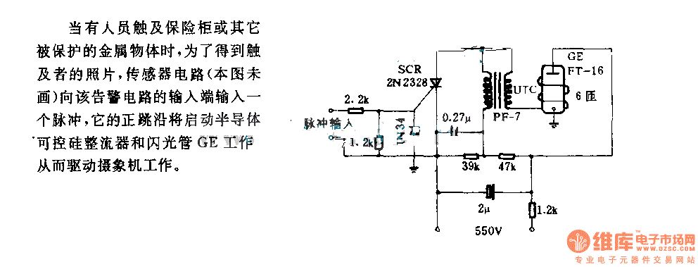
The alarm circuit diagram for safety box and other metal objects
When an individual touches the safety box or other protected metal objects, the sensor circuit generates a pulse to the alarm circuit. The positive edge of this pulse activates the semiconductor and thyristor flash GE, subsequently triggering the camera to...