


Three-start circuit current relay
#current relay
#current detection
#starting current
#electrical circuit
#relay
#sensor circuit
#current measurement
#three-stage circuit

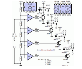
Description: The circuit illustrated in Figure 3-161 features a first stage current detection mechanism utilizing a current relay (KI1) in series with a resistor (R1). The second stage employs another current relay (KI2) in series with a resistor (R2) for current detection. Additionally, a third stage is represented by current relay (KI3) in series with a resistor (R3) for further current detection. All relays are designed to have the same pull-in current, yet they exhibit varying release currents, with KI1 having the highest release current, followed by KI2, and KI3 having the lowest.
The circuit design consists of three distinct stages, each utilizing a current relay for monitoring and controlling the current flow within the system. The first stage, featuring relay KI1 and resistor R1, is responsible for detecting the initial current level. When the current surpasses the specified threshold, the relay activates, allowing the current to flow to the subsequent stage.
In the second stage, relay KI2, in conjunction with resistor R2, serves as a secondary monitoring point. This relay is also designed to engage at a predetermined pull-in current, which is consistent with the first stage. However, it is important to note that each relay has a unique release current characteristic. KI2 will disengage at a higher current level compared to KI3, ensuring that the system maintains a specific operational threshold before allowing further current flow.
The third stage, represented by relay KI3 and resistor R3, acts as a final detection point. This relay is calibrated to respond to the lowest pull-in current of the three relays, ensuring that the system can handle lower current levels effectively. The differing release currents across the relays provide a layered approach to current management, allowing for fine-tuning of the circuit's response to varying load conditions.
Overall, the configuration of these relays and resistors creates a robust current detection system that can effectively manage and monitor electrical currents across multiple stages, ensuring reliable operation and protection of the connected circuitry. The careful selection of pull-in and release currents for each relay enhances the circuit's ability to respond dynamically to changes in current flow, thereby improving the overall efficiency and safety of the electronic system. Circuit shown in Figure 3-161. Figure, the first stage starting current detection by the current relay KIi Ri in series with the second stage starting current relay KI2 detecte d by the current series with R2, current relay Kla third stage starting from the current series with R3 detection. They have the same pull current, but have different release current, which KI1 maximum, K2 followed, Kl [3 minimum.
The circuit design consists of three distinct stages, each utilizing a current relay for monitoring and controlling the current flow within the system. The first stage, featuring relay KI1 and resistor R1, is responsible for detecting the initial current level. When the current surpasses the specified threshold, the relay activates, allowing the current to flow to the subsequent stage.
In the second stage, relay KI2, in conjunction with resistor R2, serves as a secondary monitoring point. This relay is also designed to engage at a predetermined pull-in current, which is consistent with the first stage. However, it is important to note that each relay has a unique release current characteristic. KI2 will disengage at a higher current level compared to KI3, ensuring that the system maintains a specific operational threshold before allowing further current flow.
The third stage, represented by relay KI3 and resistor R3, acts as a final detection point. This relay is calibrated to respond to the lowest pull-in current of the three relays, ensuring that the system can handle lower current levels effectively. The differing release currents across the relays provide a layered approach to current management, allowing for fine-tuning of the circuit's response to varying load conditions.
Overall, the configuration of these relays and resistors creates a robust current detection system that can effectively manage and monitor electrical currents across multiple stages, ensuring reliable operation and protection of the connected circuitry. The careful selection of pull-in and release currents for each relay enhances the circuit's ability to respond dynamically to changes in current flow, thereby improving the overall efficiency and safety of the electronic system. Circuit shown in Figure 3-161. Figure, the first stage starting current detection by the current relay KIi Ri in series with the second stage starting current relay KI2 detecte d by the current series with R2, current relay Kla third stage starting from the current series with R3 detection. They have the same pull current, but have different release current, which KI1 maximum, K2 followed, Kl [3 minimum.

power window 3 prong safety relay
The power windows operate slowly, but connecting 12 volts directly to the motors allows them to function properly. A previous discussion mentioned using a common 5-pin ice cube relay, but there was no confirmation of its effectiveness. The power window...
Reducing Relay Power Consumption
This circuit demonstrates that microprocessors, personal computers, and the latest ultra-accurate digital-to-analog converters (DACs) are excessive for the task of sequentially controlling four relays.
The circuit utilizes a simple microcontroller or a basic timer IC to manage the operation of four...

Trip Circuit of a Circuit Breaker
Consider a simplified circuit of a typical relay, which is usually part of a three-phase circuit with a complex contact system. The provided diagram illustrates a single-phase simplified circuit to clarify the basic operation of a relay. Part A represents...

Photo Light with Relay
The circuit below uses a CMOS dual D flip flop (CD4013) to toggle a relay or other load with a momentary push button. Several push buttons can be wired in parallel to control the relay from multiple locations. More: The...

Electromechanical relay logic
In ladder logic symbolism, an electromechanical relay coil is depicted as a circle, while the contact(s) actuated by the coil are represented by two parallel lines, resembling a capacitor symbol. To interpret a ladder logic diagram, it is essential to...

Two Simple Relay Based Motorcycle Alarms circuit
Relays can be utilized to protect motorcycles and have various other applications. When using relays with 6-volt coils, they provide security for "Classic Bikes." The alarms are compact, with completed boards occupying approximately half a cubic inch (8 cc). The...

DC relay delayed release circuit 2 b
The circuit depicted in Figure 6-24 includes a relay coil with both ends connected in parallel to a resistor (Rf) or an auxiliary diode (VD). This configuration is intended to enhance power after a short circuit occurs in the coil...

12V Relay on 6V power supply
This circuit allows a 12v relay to operate on a 6v or 9v supply. Most 12v relays need about 12v to "pull-in" but will "hold" on about 6v. The 220u charges via the 2k2 and bottom diode. When an input...

Mathematical approch to measuring current voltage and resistance of mixed series and parallel
There is one significant low-impedance node in the entire circuit, referred to as 0V, located at the frame and the intersection in the middle. The upper voltage source is connected to this midpoint through a 1kΩ resistor, indicating that the...