


Tone detector
#tone detector
#bandpass filter
#Schmitt Trigger
#ac-to-dc
#amplifier
#frequency detection
#rectifier
#filter
#audio frequency

Description: The detector circuit consists of a two-amplifier multiple feedback bandpass filter followed by an AC-to-DC detector section and a Schmitt Trigger. The bandpass filter, with a quality factor (Q) greater than 100, allows only 500 Hz inputs, which are subsequently rectified by diode D1 and filtered by resistor R9 and capacitor C1. This filtering action, combined with a trigger level of 5 V for the Schmitt Trigger, ensures that a minimum of 55 cycles of a 500 Hz input must be present before the output responds to a tone input.
The detector circuit is designed to selectively filter and process signals of a specific frequency while rejecting unwanted noise. The two-amplifier multiple feedback bandpass filter is critical in achieving a high Q factor, which enhances the circuit's selectivity and sensitivity to the desired frequency of 500 Hz. This filter configuration typically employs operational amplifiers configured in a feedback loop, allowing for precise tuning of both the center frequency and bandwidth.
The rectification stage, implemented using diode D1, converts the AC signal output from the bandpass filter into a DC voltage. The subsequent filtering by resistor R9 and capacitor C1 smoothens the rectified signal, providing a stable DC level that can be further processed. The choice of R9 and C1 values is crucial, as they determine the time constant of the filter, affecting how quickly the circuit responds to changes in the input signal.
The Schmitt Trigger serves as a level detector, ensuring that only signals that exceed a specific threshold (5 V in this case) will trigger a response. This hysteresis characteristic of the Schmitt Trigger prevents false triggering from noise or small fluctuations in the input signal, enhancing the reliability of the circuit. The requirement for at least 55 cycles of the 500 Hz input ensures that the circuit only activates in the presence of a stable and consistent tone, further improving the accuracy of detection.
Overall, this detector circuit is well-suited for applications requiring precise frequency detection and reliable output response, making it ideal for various electronic systems where tone recognition is essential.The detector circuit is made up a two-amplifier multiple feedback bandpass filter followed by an ac-to-dc detector section and a Schmitt Trigger. The bandpass filter (with a Q of greater than 100) passes only 5Q0 Hz inputs whch are in turn rectified by Dl and filtered by R9 and Ca
This filtering action in combination with the trigger level of 5 V for the Schmitt device insures that at least 55 cycles of 500 Hz input must be present before the output will react to a tone input.
The detector circuit is designed to selectively filter and process signals of a specific frequency while rejecting unwanted noise. The two-amplifier multiple feedback bandpass filter is critical in achieving a high Q factor, which enhances the circuit's selectivity and sensitivity to the desired frequency of 500 Hz. This filter configuration typically employs operational amplifiers configured in a feedback loop, allowing for precise tuning of both the center frequency and bandwidth.
The rectification stage, implemented using diode D1, converts the AC signal output from the bandpass filter into a DC voltage. The subsequent filtering by resistor R9 and capacitor C1 smoothens the rectified signal, providing a stable DC level that can be further processed. The choice of R9 and C1 values is crucial, as they determine the time constant of the filter, affecting how quickly the circuit responds to changes in the input signal.
The Schmitt Trigger serves as a level detector, ensuring that only signals that exceed a specific threshold (5 V in this case) will trigger a response. This hysteresis characteristic of the Schmitt Trigger prevents false triggering from noise or small fluctuations in the input signal, enhancing the reliability of the circuit. The requirement for at least 55 cycles of the 500 Hz input ensures that the circuit only activates in the presence of a stable and consistent tone, further improving the accuracy of detection.
Overall, this detector circuit is well-suited for applications requiring precise frequency detection and reliable output response, making it ideal for various electronic systems where tone recognition is essential.The detector circuit is made up a two-amplifier multiple feedback bandpass filter followed by an ac-to-dc detector section and a Schmitt Trigger. The bandpass filter (with a Q of greater than 100) passes only 5Q0 Hz inputs whch are in turn rectified by Dl and filtered by R9 and Ca
This filtering action in combination with the trigger level of 5 V for the Schmitt device insures that at least 55 cycles of 500 Hz input must be present before the output will react to a tone input.

Precision polarity switching circuit by conventional elements
The loop gain of the operational amplifier (OP) is primarily influenced by the ratio of the input resistor to the feedback resistor. Consequently, any resistance error can lead to a corresponding gain error, which necessitates the use of high-precision resistors,...

Schmitt trigger zero crossing detector
This circuit features a 100 mV hysteresis, suitable for applications demanding rapid output transition times despite slow input signals. The hysteresis loop minimizes false triggering caused by noise on the input. The accompanying waveforms illustrate the trip points established by...

Adjustable half-wave rectifier charging circuit
The adjustment potentiometer RP is utilized to modify the charging current.
The adjustment potentiometer, designated as RP, serves a critical function in regulating the charging current within an electronic circuit. This component is typically a variable resistor that allows for fine-tuning...

simple-amplifier-with-c945mje340-and.html
This simple amplifier delivers good sound quality with a power output of approximately 10 to 14 Watts and operates on a supply voltage of about 34 to 36 Volts DC. It requires a preamplifier due to its limited advanced features....

Self Oscillating Amplifier for Distortion Testing
The circuit is based on a simple inductor-capacitor filter circuit, and needs only a pot and a small light bulb to set and stabilise the oscillation. The frequency is fixed, and with a good inductor should be capable of very...
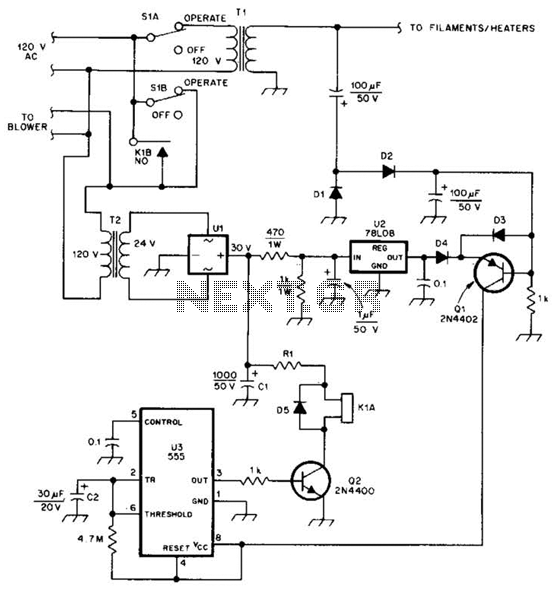
Amplifier Cool-Down Circuit Circuit
This cool-down relay circuit utilizes an integrated circuit (IC) timer to control a relay, which maintains the operation of the blower for a specified time delay determined by timer U3. The capacitance value of C2 can be adjusted to either...

audio amp
Install the red LED at D2. Align the flat side of the LED with the PCB outline. Install a jumper wire at R4 and install a 220µF electrolytic capacitor at C8 with the negative side connected to ground. Connect pin...

Wide band high frequency amplifier circuit
This is a wideband high-frequency amplifier circuit designed for a frequency range between 75-150 MHz. It utilizes a PNP transistor amplifier to enhance signal strength before it reaches the receiver of devices such as phones, FM radios, or amateur radios....

RAZOR SHARP CW FILTER
The circuit comprises four stages of active bandpass filtering, utilizing two A747 integrated-circuit dual operational amplifiers. It incorporates a simple threshold detector, consisting of diodes D1 and D2, positioned between stages 2 and 3 to minimize low-level background noise. Each...