


Triggers Circuits
#photogate
#sound trigger
#trigger circuit
#beam break
#elastic cord
#flash
#photography
#precision measurement
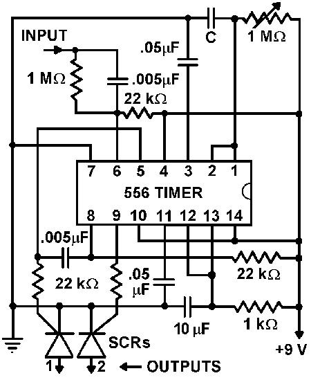
Description: An advantage of a photogate over a sound trigger is that the former activates based on the exact position of the object that interrupts the beam. For instance, the shape of a snapped elastic cord can be captured as it travels through the beam. Although a sensitive sound trigger could also record the shape, the position of the cord when the flash is triggered would be much less predictable. A challenge when utilizing a photogate arises if the event to be captured occurs after the light beam is broken. For example, to photograph a liquid drop as it splashes into a pool, the photogate must be positioned above the pool. If the drop's passage through the photogate is the trigger for the flash unit, a delay would be necessary to allow the drop to reach the pool. This issue can be resolved by employing a delay circuit. The delay circuit utilizes a 556 timer, which is an integrated circuit composed of two 555 timers. Grounding the input initiates the first timer, producing a square pulse at output 1 (pin 5). The pulse width is determined by the selection of capacitance, C, and the setting of the 1-MΩ variable resistor. Output 1 is connected to the trigger (pin 8) of the second timer through a 0.005-µF capacitor. When output 1 drops to zero, the second timer activates, generating a 10-ms pulse at output 2 (pin 9). This pulse controls an SCR to discharge a flash unit. Output 1 can also be utilized to trigger an SCR for an immediate flash discharge, with the minimum time interval between the immediate and delayed discharges being approximately 0.2 ms. When the photogate and delay unit are used in conjunction, the photogate output serves as the input for the delay unit. The value of C selected for the delay circuit is contingent upon the specific experiment. For example, if a drop of milk passes through the photogate and falls half a meter into a pool, a delay of around 0.3 seconds is necessary to capture the splash. Using a 0.5-µF capacitor for C allows for a range of time intervals up to 0.5 seconds. The time delay in seconds is approximately equal to the product of the variable resistance in megohms and C in microfarads.
The described circuit employs a photogate and a delay mechanism to accurately capture transient events such as splashes. The photogate operates by emitting a beam of light that, when interrupted by an object, triggers the associated circuitry. The first stage of the circuit involves a 556 timer IC, which contains two 555 timers. The initiation of the first timer occurs upon grounding its input, resulting in a square wave output at pin 5. The pulse width generated is adjustable based on the capacitance selected (C) and the resistance set by the variable resistor (1 MΩ).
The output from the first timer is coupled to the second timer's trigger input through a coupling capacitor (0.005 µF), ensuring that the pulse is transmitted without affecting the timing characteristics. Upon the completion of the first timer's pulse, the second timer activates, producing a short pulse (10 ms) at its output (pin 9). This pulse is critical for controlling a silicon-controlled rectifier (SCR), which acts as a switch to discharge a flash unit, thereby capturing the desired event.
Furthermore, the circuit allows for immediate flash discharge, which can be triggered directly from the first output. The minimal time interval between the immediate and delayed flashes is about 0.2 ms, enabling precise timing control for high-speed events. The interaction between the photogate and the delay circuit is pivotal; the photogate output serves as the delay circuit's input, thus ensuring that the timing can be adjusted based on the specific dynamics of the experiment being conducted.
The selection of the capacitor (C) is crucial for determining the delay duration. For instance, in an experiment involving a droplet of milk falling from a height of half a meter, a delay of approximately 0.3 seconds is required to adequately capture the splash upon impact. By using a 0.5 µF capacitor, the circuit can provide a range of delay times up to 0.5 seconds, allowing flexibility for various experimental conditions. The relationship between the resistance and capacitance values is defined by the formula for time delay, which states that the delay in seconds is approximately equal to the product of the variable resistance in megohms and the capacitance in microfarads. This systematic approach ensures that the circuit can be effectively tailored to meet the needs of different applications in high-speed photography and motion analysis.An advantage that a photogate has over a sound trigger is that the former triggers on the precise location of the object that breaks the beam. For example, the shape of a snapped elastic cord can be photographed as it passes through the beam. While a sensitive sound trigger could also capture the shape, the location of the cord when the flash disc
harged would be much less predictable. A complication when using a photogate occurs if the event to be photographed occurs after the breaking of the light beam. For example, if a liquid drop is to be photographed as it splashes into a pool of liquid, the photogate must be located above the pool.
If the passage of the drop through the photogate were to be the event that triggered the flash unit, there would have to be a delay to allow the drop time to reach the pool. This difficulty can be overcome by using a delay circuit. The delay circuit shown above uses a 556 timer, an IC consisting of two 555 timers. Grounding the input starts the first timer and produces a square pulse at output 1 (pin 5). The width of the pulse is determined by the choice of capacitance, C, and the setting of the 1-M © variable resistor.
Output 1 is coupled to the trigger (pin 8) of the second timer through a 0. 005- µf capacitor. When output 1 falls to zero, the second timer starts, producing a 10-ms pulse at output 2 (pin 9). This pulse gates an SCR to discharge a flash unit. Output 1 can also be used to gate an SCR in order to provide an immediate flash discharge. The smallest time interval between the immediate and delayed discharges is about 0. 2 ms. When using the photogate and delay unit together, the output of the photogate becomes the input of the delay unit. The value of C chosen for the delay circuit depends on the experiment being conducted. If, for example, a drop of milk passes through the photogate and falls a distance of a half meter into a pool, a delay of about 0.
3 s is required to capture the splash. Using a 0. 5- µf capacitor for C provides a selection of time intervals up to 0. 5 s. (The time delay in seconds is approximately equal to the product of the variable resistance in megohms and C in microfarads. )
The described circuit employs a photogate and a delay mechanism to accurately capture transient events such as splashes. The photogate operates by emitting a beam of light that, when interrupted by an object, triggers the associated circuitry. The first stage of the circuit involves a 556 timer IC, which contains two 555 timers. The initiation of the first timer occurs upon grounding its input, resulting in a square wave output at pin 5. The pulse width generated is adjustable based on the capacitance selected (C) and the resistance set by the variable resistor (1 MΩ).
The output from the first timer is coupled to the second timer's trigger input through a coupling capacitor (0.005 µF), ensuring that the pulse is transmitted without affecting the timing characteristics. Upon the completion of the first timer's pulse, the second timer activates, producing a short pulse (10 ms) at its output (pin 9). This pulse is critical for controlling a silicon-controlled rectifier (SCR), which acts as a switch to discharge a flash unit, thereby capturing the desired event.
Furthermore, the circuit allows for immediate flash discharge, which can be triggered directly from the first output. The minimal time interval between the immediate and delayed flashes is about 0.2 ms, enabling precise timing control for high-speed events. The interaction between the photogate and the delay circuit is pivotal; the photogate output serves as the delay circuit's input, thus ensuring that the timing can be adjusted based on the specific dynamics of the experiment being conducted.
The selection of the capacitor (C) is crucial for determining the delay duration. For instance, in an experiment involving a droplet of milk falling from a height of half a meter, a delay of approximately 0.3 seconds is required to adequately capture the splash upon impact. By using a 0.5 µF capacitor, the circuit can provide a range of delay times up to 0.5 seconds, allowing flexibility for various experimental conditions. The relationship between the resistance and capacitance values is defined by the formula for time delay, which states that the delay in seconds is approximately equal to the product of the variable resistance in megohms and the capacitance in microfarads. This systematic approach ensures that the circuit can be effectively tailored to meet the needs of different applications in high-speed photography and motion analysis.An advantage that a photogate has over a sound trigger is that the former triggers on the precise location of the object that breaks the beam. For example, the shape of a snapped elastic cord can be photographed as it passes through the beam. While a sensitive sound trigger could also capture the shape, the location of the cord when the flash disc
harged would be much less predictable. A complication when using a photogate occurs if the event to be photographed occurs after the breaking of the light beam. For example, if a liquid drop is to be photographed as it splashes into a pool of liquid, the photogate must be located above the pool.
If the passage of the drop through the photogate were to be the event that triggered the flash unit, there would have to be a delay to allow the drop time to reach the pool. This difficulty can be overcome by using a delay circuit. The delay circuit shown above uses a 556 timer, an IC consisting of two 555 timers. Grounding the input starts the first timer and produces a square pulse at output 1 (pin 5). The width of the pulse is determined by the choice of capacitance, C, and the setting of the 1-M © variable resistor.
Output 1 is coupled to the trigger (pin 8) of the second timer through a 0. 005- µf capacitor. When output 1 falls to zero, the second timer starts, producing a 10-ms pulse at output 2 (pin 9). This pulse gates an SCR to discharge a flash unit. Output 1 can also be used to gate an SCR in order to provide an immediate flash discharge. The smallest time interval between the immediate and delayed discharges is about 0. 2 ms. When using the photogate and delay unit together, the output of the photogate becomes the input of the delay unit. The value of C chosen for the delay circuit depends on the experiment being conducted. If, for example, a drop of milk passes through the photogate and falls a distance of a half meter into a pool, a delay of about 0.
3 s is required to capture the splash. Using a 0. 5- µf capacitor for C provides a selection of time intervals up to 0. 5 s. (The time delay in seconds is approximately equal to the product of the variable resistance in megohms and C in microfarads. )

An automatic flash indicating circuit
The DW L11 capacitor steps down voltage into the Jenru half crossing according to Yin electrical specifications. After receiving power at the bin CI SH output terminal, it regulates the voltage to liVI/r j, ensuring a right cut in blood...

Flash Slave Trigger
Flash slaves are used when you need to supplement one flash unit with one or several more. This slave trigger simply triggers those other units. It does this by "seeing" the first flash (using a phototransistor) and triggering the other...

Trigger Circuit Controls Stop-Motion Camera System
This version of the trigger circuit for the stop-motion camera system utilizes an electret microphone for sonic input, although it can be replaced with an LED and photodiode pair for optical triggering. A recent home-built project involved constructing a stop-motion...

Sound light-flash trigger
Sound input to the microphone triggers the IC monostable circuit, which subsequently triggers an SCR, and hence the flash, after a time delay. This delay is adjustable by varying the monostable on-time from 5 milliseconds to 200 milliseconds.
The circuit described...

Fill light indoor photography circuit
Engaged in indoor portrait photography, practitioners often find that using a single camera can result in images lacking depth and layering. To achieve better photographic outcomes, multiple auxiliary lighting sources are typically arranged around the subject. The following describes a...

Kodak Flash circuit
This flash circuit is a typical camera flash.
This flash circuit functions as a high-voltage power supply for camera flash units, enabling the rapid discharge of energy to produce a bright flash of light. The primary components of a typical camera...
Flash Slave Trigger
Flash slaves are used when you need to supplement one flash unit with one or several more. This slave trigger simply triggers those other units. It does this by "seeing" the first flash (using a phototransistor) and triggering the other...

Flash slave driver
In photography, a separate flash, triggered by the light of a master flash, is often required to provide additional light and fill in shadows. The sensitivity of this circuit depends on the proximity of the master flash and the value...
circuit trigger camera phone pda mp3
In night photography, long exposures are common, sometimes lasting several seconds to several minutes. HDR techniques often require taking a series of nine or more photos. Holding a remote trigger for an extended period can be tedious, leading to the...