


ultrasonic electrostatic transducer for
#ultrasonic
#transducer
#LM1812
#pulse/echo-ranging
#sensor
#echo detection
#ranging applications
#ultrasonic transceiver

Description: This is a complete design circuit for an ultrasonic transceiver utilized in various pulse/echo-ranging applications. The circuit features the LM1812, which transmits a burst of oscillations through transducer X1. Subsequently, the same transducer listens for a return echo. If an echo of sufficient amplitude is detected, the LM1812 detector generates a pulse (pin 16) approximately equal in width to the original burst. The distance to the reflecting object affects the timing of the return echo; the closer the object, the sooner the echo returns. With the specified values and components, the circuit achieves a range of approximately 4 inches to 30 feet. Inductor L6 resonates at frequencies between 50 to 60 kHz, in conjunction with the 500-pF capacitance of X1. Inductor L1 is tuned to this frequency by monitoring for maximum echo sensitivity at pin 1 using an oscilloscope. [Circuit diagram source: National Semiconductor Application Notes and Seekic.com]
The ultrasonic transceiver circuit is designed to operate effectively in pulse/echo-ranging applications, making it suitable for various distance measurement tasks. The LM1812 integrated circuit serves as the core component, functioning as both a transmitter and a receiver. When activated, it sends a burst of ultrasonic waves through the transducer X1, which is capable of both emitting and receiving sound waves.
The operation begins with the LM1812 generating a high-frequency oscillation signal, which is transmitted as a burst through transducer X1. This transducer converts the electrical signal into ultrasonic sound waves. Upon encountering an object, these waves reflect back toward the transducer, where they are converted back into electrical signals.
The LM1812 is configured to detect these returning echoes. When an echo of sufficient amplitude is received, the LM1812 activates its output at pin 16, producing a pulse that corresponds in width to the transmitted burst. The timing of this pulse is critical, as it is directly related to the distance of the reflecting object. A shorter time delay indicates a closer object, while a longer delay suggests a greater distance.
The circuit is designed to operate effectively over a range of approximately 4 inches to 30 feet, making it versatile for various applications. The tuning of inductor L6 is essential for achieving resonance at frequencies between 50 to 60 kHz, which is necessary for optimal transducer performance. The 500-pF capacitance of transducer X1 works in conjunction with L6 to establish the desired resonant frequency.
Inductor L1 plays a crucial role in fine-tuning the circuit's sensitivity. By adjusting L1 and observing the output signal at pin 1 with an oscilloscope, the user can optimize the circuit for maximum echo sensitivity. This adjustment ensures that the circuit can accurately detect echoes from objects at varying distances, enhancing the overall performance of the ultrasonic transceiver.
Overall, this ultrasonic transceiver circuit exemplifies a well-designed system capable of precise distance measurements, suitable for applications ranging from industrial sensing to consumer electronics. The careful selection of components and tuning techniques contributes to its effectiveness in pulse/echo-ranging scenarios.This is a complete design circuit for a complete ultrasonic transceiver used in a variety of pulse/echo-ranging applications. Here`s the figure of the circuit; In this circuit, the LM1812 transmits a burst of oscillations with transducer X1.
Then, using the same X1, listens for a return echo. If an echo of sufficient amplitude is received, the LM1 812 detector produces a pulse (pin 16) of about the same width as the original burst. The closer the reflecting object, the earlier the return echo. Using the values and parts shown, the circuit has a range of about 4 inches to 30 feet. L6 resonates at 50 to 60 kHz, with the 500-pF capacitance of X1. L1 is tuned to this frequency by watching for maximum echo sensitivity with a scope at pin 1. [Circuit diagram source: National Semiconductor Application Notes and Seekic. com]
The ultrasonic transceiver circuit is designed to operate effectively in pulse/echo-ranging applications, making it suitable for various distance measurement tasks. The LM1812 integrated circuit serves as the core component, functioning as both a transmitter and a receiver. When activated, it sends a burst of ultrasonic waves through the transducer X1, which is capable of both emitting and receiving sound waves.
The operation begins with the LM1812 generating a high-frequency oscillation signal, which is transmitted as a burst through transducer X1. This transducer converts the electrical signal into ultrasonic sound waves. Upon encountering an object, these waves reflect back toward the transducer, where they are converted back into electrical signals.
The LM1812 is configured to detect these returning echoes. When an echo of sufficient amplitude is received, the LM1812 activates its output at pin 16, producing a pulse that corresponds in width to the transmitted burst. The timing of this pulse is critical, as it is directly related to the distance of the reflecting object. A shorter time delay indicates a closer object, while a longer delay suggests a greater distance.
The circuit is designed to operate effectively over a range of approximately 4 inches to 30 feet, making it versatile for various applications. The tuning of inductor L6 is essential for achieving resonance at frequencies between 50 to 60 kHz, which is necessary for optimal transducer performance. The 500-pF capacitance of transducer X1 works in conjunction with L6 to establish the desired resonant frequency.
Inductor L1 plays a crucial role in fine-tuning the circuit's sensitivity. By adjusting L1 and observing the output signal at pin 1 with an oscilloscope, the user can optimize the circuit for maximum echo sensitivity. This adjustment ensures that the circuit can accurately detect echoes from objects at varying distances, enhancing the overall performance of the ultrasonic transceiver.
Overall, this ultrasonic transceiver circuit exemplifies a well-designed system capable of precise distance measurements, suitable for applications ranging from industrial sensing to consumer electronics. The careful selection of components and tuning techniques contributes to its effectiveness in pulse/echo-ranging scenarios.This is a complete design circuit for a complete ultrasonic transceiver used in a variety of pulse/echo-ranging applications. Here`s the figure of the circuit; In this circuit, the LM1812 transmits a burst of oscillations with transducer X1.
Then, using the same X1, listens for a return echo. If an echo of sufficient amplitude is received, the LM1 812 detector produces a pulse (pin 16) of about the same width as the original burst. The closer the reflecting object, the earlier the return echo. Using the values and parts shown, the circuit has a range of about 4 inches to 30 feet. L6 resonates at 50 to 60 kHz, with the 500-pF capacitance of X1. L1 is tuned to this frequency by watching for maximum echo sensitivity with a scope at pin 1. [Circuit diagram source: National Semiconductor Application Notes and Seekic. com]

Ultrasonic atomizer 2
The ultrasonic atomizer circuit consists of a power supply circuit, control circuit, water detection alarm circuit, and an ultrasonic oscillator, as illustrated in Figure 3-190. The power supply circuit includes a power switch (S), fuses (FU1, FU2), a timer (Q),...
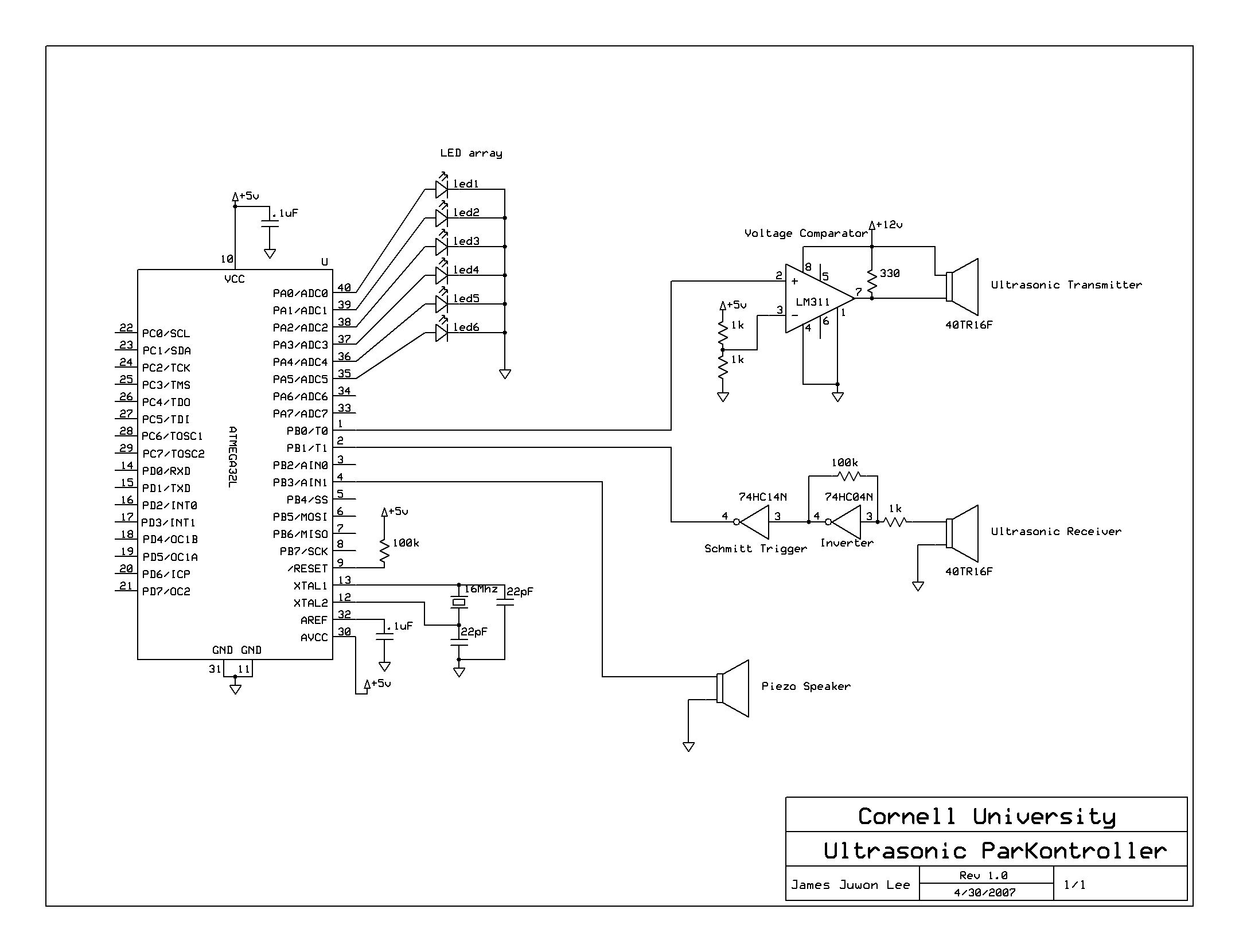
Ultrasonic Parking controller
A series of five short pulses blasted by the microcontroller only has 5V amplitude, which will be attenuated down to less than 20 mV when received by the receiver circuit. Hence, LM311 voltage comparator was used for signal amplification before...

Medical ultrasonic atomizer 3
The medical ultrasonic atomizer circuit consists of a power supply circuit, a low side liquid level protection control circuit, an ultrasonic oscillator, and a fan drive circuit, as depicted in figure 9-112. The power supply circuit includes a power supply...

Ultrasonic drilling machine circuit diagram 2
The ultrasonic drilling machine circuit consists of a power supply circuit, an ultrasonic oscillator circuit, a preamplifier, a promoting amplifier circuit, and a power amplifier output circuit, as depicted in the accompanying diagram. The ultrasonic oscillator circuit is made up...

Ultrasonic Liquid Level Indicator Circuit Composed Of NE555
The image depicts an ultrasonic liquid level indicator circuit. This circuit consists of an ultrasonic transmitter circuit and a receiver circuit. The ultrasonic transmitter circuit includes a 555 timer, resistor R1, variable resistor W1, capacitor C1, and the ultrasonic transmitter...

High-accuracy ultrasonic range measurement system because of ߀?s C OS and ARM processor
The mobile robot is designed to operate in unknown and uncertain environments, featuring autopilot capabilities while avoiding obstacles. It utilizes ultrasonic sensors for range finding due to their simplicity, speed, and cost-effectiveness in information processing. These sensors facilitate functions such...

Ultrasonic drilling machine circuit
The ultrasonic drilling machine is essential machinery in the dairy industry for processing jewelry, primarily for natural stones, crystal agate, jade, and glass products. This machine is particularly effective for high-hardness materials, enabling both drilling and engraving. The following outlines...
Medical ultrasonic atomizer 3
The medical ultrasonic atomizer circuit consists of a power supply circuit, a low side liquid level protection control circuit, an ultrasonic oscillator, and a fan drive circuit, as depicted in figure 9-112. The power supply circuit includes a power supply...
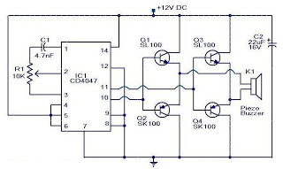
circuit ultrasonic mosquito
This is a small circuit designed as an insect repellent, targeting mosquitoes and birds by producing high-frequency audio signals. These signals interfere with the hearing of insects, making it unbearable for them, causing them to flee. The operation of this...