


Visible-Light Receiver Circuit
#visible-light
#receiver
#phototransistor
#amplitude-modulated
#audio amplifier
#emitter-follower
#parabolic reflector
#npn

Description: This receiver for amplitude-modulated light signals utilizes a phototransistor Q1 mounted within a parabolic reflector to enhance its range. Any NPN phototransistor is suitable for this application. An emitter-follower configuration using Q2 drives an amplifier stage Q3. The output from Q3 is directed to a volume control resistor R7, followed by an audio amplifier U1. A power supply voltage of 9 to 12 volts is recommended for optimal operation of the receiver.
The described circuit operates by detecting amplitude-modulated light signals, which are typically generated by an infrared LED or similar light source. The phototransistor Q1 serves as the primary sensing element, converting the incoming light signals into electrical current. The parabolic reflector enhances the effective range by directing more light onto the phototransistor, thus improving sensitivity and performance in various lighting conditions.
The emitter-follower transistor Q2 is configured to provide impedance matching between the phototransistor and the subsequent amplifier stage. This configuration ensures that the output from Q1 can drive Q3 effectively, allowing for a stronger signal to be amplified. The amplifier Q3 is crucial for boosting the weak signals received from the phototransistor to a level suitable for processing.
Following amplification, the output signal is passed through a volume control resistor R7, allowing for user adjustment of the audio output level. This control is essential for tailoring the listening experience to the user's preference and ensuring that the audio signal is not too loud or too soft.
Finally, the audio amplifier U1 is responsible for driving the speaker or headphones, converting the amplified electrical signals into audible sound. The recommended power supply voltage range of 9 to 12 volts ensures that all components operate within their specified limits, providing reliable performance and longevity for the receiver circuit.
This circuit design is versatile and can be adapted for various applications, including wireless audio transmission systems, remote control devices, and other light-based communication systems. This receiver for amplitude-modulated light signals uses phototransistor Ql mounted in a parabolic reflector (to increase range). Any npn phototransistor should work. Emitter-follower Q2 drives amplifier Q3. The output from Q3 feeds volume control R7 and audio.amplifier Ul. A 9- to 12-V supply is recommended for the receiver.
The described circuit operates by detecting amplitude-modulated light signals, which are typically generated by an infrared LED or similar light source. The phototransistor Q1 serves as the primary sensing element, converting the incoming light signals into electrical current. The parabolic reflector enhances the effective range by directing more light onto the phototransistor, thus improving sensitivity and performance in various lighting conditions.
The emitter-follower transistor Q2 is configured to provide impedance matching between the phototransistor and the subsequent amplifier stage. This configuration ensures that the output from Q1 can drive Q3 effectively, allowing for a stronger signal to be amplified. The amplifier Q3 is crucial for boosting the weak signals received from the phototransistor to a level suitable for processing.
Following amplification, the output signal is passed through a volume control resistor R7, allowing for user adjustment of the audio output level. This control is essential for tailoring the listening experience to the user's preference and ensuring that the audio signal is not too loud or too soft.
Finally, the audio amplifier U1 is responsible for driving the speaker or headphones, converting the amplified electrical signals into audible sound. The recommended power supply voltage range of 9 to 12 volts ensures that all components operate within their specified limits, providing reliable performance and longevity for the receiver circuit.
This circuit design is versatile and can be adapted for various applications, including wireless audio transmission systems, remote control devices, and other light-based communication systems. This receiver for amplitude-modulated light signals uses phototransistor Ql mounted in a parabolic reflector (to increase range). Any npn phototransistor should work. Emitter-follower Q2 drives amplifier Q3. The output from Q3 feeds volume control R7 and audio.amplifier Ul. A 9- to 12-V supply is recommended for the receiver.

TBA810 - 7 Watt Audio Amplifier Circuit
This circuit is a 7 Watt audio amplifier that is simple and easy to construct. It utilizes the TBA810 as the primary component, supported by a few passive components. The amplifier operates effectively, and the necessary kits and components are...

TDA Amplifier Circuits
The TDA integrated circuit series is highly regarded and widely utilized in amplifier designs and projects. TDA audio amplifier circuits are primarily produced by Philips and SGS-THOMSON. The most commonly used ICs include the TDA2030 and TDA2003 for small audio...

200 Watt High Quality Audio Amplifier
This high-power audio amplifier provides top-quality performance for loudspeakers with an impedance of 4 to 8 ohms. It operates within a frequency range of 20 to 20,000 Hz and requires a voltage supply of 24 to 36 volts, with a...
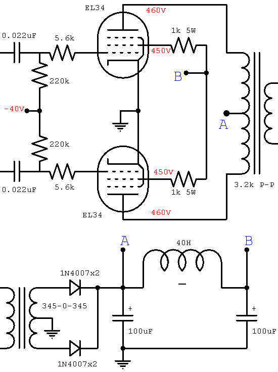
marshall jcm800 2204 power amp
The JCM800 power amplifier has a rich heritage, drawing from classic amplifiers such as the Fender Bassman 5F6-A, the Marshall JTM45, the Model 1962 "Bluesbreaker," and the Model 1987 "Plexi." It features significantly enhanced power supply filtering compared to its...

Tone-control audio amplifier
The circuit effectively utilizes the high slew rate, wide bandwidth, high input impedance, and high output voltage capability of the CA3140 BiMOS operational amplifier. The wideband gain of this circuit is equal to the ultimate boost or cut plus one,...

Low cost 20 w audio amplifier
This simple and inexpensive audio amplifier can be constructed using a couple of TO-220 monolithic Darlington transistors for the push-pull output stage. The frequency response is flat within 1 dB from 30 Hz to 200 kHz, with typical harmonic distortion...

Booster Amplifier For Car Stereo Use Circuit
Only one channel of this circuit is shown. The other is practically identical. The input to the circuit, taken from the speaker output of a car radio, is divided into two paths. In one path, a high-power divider network (comprising...
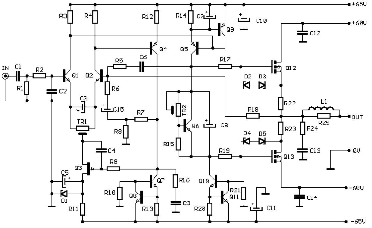
100W FET audio amplifier
This balanced preamplifier circuit is designed to amplify low-level audio signals (from 0 dB to 20 dB) and features balanced inputs and outputs. The design utilizes standard components that are readily available in the electronics market.
The balanced preamplifier circuit serves...

50w stereo audio amplifier circuit
A 1000 Watts audio power amplifier circuit designed for outdoor use. A circuit diagram is needed urgently to facilitate the construction of this high-power amplifier, which is a personal passion project.
The design of a 1000 Watts audio power amplifier circuit...