


Visual Target Tracking Sysyem
#visual tracking
#camera
#gimbal
#target detection
#digital control
#monitor
#overlay
#modular design

Description: The Visual Target Tracking System (VTTS) is designed for visually tracking targets using a gimbal-mounted camera and digital control circuitry. A small black and white camera is mounted on a stand that allows movement in two directions. When an object enters the camera's field of view, the camera adjusts its position to center the object. The camera's movement is displayed on a television monitor, which shows both a center square and a crosshair overlay on the object. The VTTS comprises four distinct modules: the digitizer, target detection, output unit, and camera control. The digitizer processes an NTSC video signal from a standard video camera and outputs a 64x64 pixel grid of black and white pixels for image detection. It produces a 7-bit X address, a 6-bit Y address line, a data line, and communication signals, including data_available and wait. The original design intended for a resolution of 192x128 (8 bits X, 7 bits Y), but this was reduced to 64x64 for implementation, although the digitizer can still capture 192x128 pixels. The digitizer generates two communication signals alongside the pixel address and data. The wait signal remains high while the digitizer buffers the next NTSC frame, allowing other modules to perform necessary computations for image detection and crosshair overlay. When the wait signal goes low, new data and address information is transmitted, and the data_available signal indicates valid information on the data and address lines. The digitizer stabilizes the address and data lines while data_available is high. The NTSC standard for broadcasting television signals in the United States was proposed in 1940 and standardized in 1953. NTSC frames consist of 525 horizontal scan lines, divided into two fields of 262.5 lines each, with even and odd lines interlaced. Each second, 30 frames (or 60 fields) are transmitted, with the first 22 horizontal lines in each frame being blank to allow the electron beam to return to the top left corner of the screen. The active video portion of NTSC consists of 480 horizontal lines (240 per frame) of continuous voltage levels, transmitted using a single wire and 6 MHz of bandwidth. Each horizontal line concludes with a horizontal sync pulse of -1 Volt.
The Visual Target Tracking System (VTTS) employs a modular architecture that enhances its functionality and flexibility for target tracking applications. The system's core components include the digitizer, which is responsible for converting the NTSC video signal into a manageable pixel grid. This digitizer is designed to operate in both a high-resolution mode (192x128) and a standard operational mode (64x64), allowing for adaptability based on the specific requirements of the tracking task.
The digitizer's output comprises a 7-bit X address and a 6-bit Y address, which are essential for pinpointing the location of the target within the pixel grid. The data line carries the pixel information, while the communication signals—data_available and wait—facilitate synchronization between the digitizer and the other modules. The wait signal indicates when the digitizer is processing data, allowing the target detection and camera control modules to execute their functions without interference.
The target detection module analyzes the pixel data received from the digitizer to identify the presence and position of targets within the camera's field of view. This module may utilize algorithms for edge detection, motion detection, or pattern recognition to accurately track the target's movement.
The output unit is responsible for rendering the processed information onto a display, providing real-time feedback to the operator. This unit overlays the crosshair and center square on the video feed, ensuring that the operator can easily visualize the target's position.
The camera control module adjusts the gimbal-mounted camera's orientation based on the target's position, ensuring that the target remains centered within the camera's view. This control system may utilize servo motors or stepper motors to achieve precise movements in both the horizontal and vertical axes.
The entire system operates under the NTSC standard, which defines the timing and format of the video signal. The synchronization of the various components is critical for maintaining the integrity of the target tracking process. The interlacing of even and odd lines in the NTSC signal allows for efficient use of bandwidth while still delivering a high-quality image.
In summary, the VTTS is a sophisticated system that integrates various electronic modules to achieve effective target tracking. Its design allows for adaptability in resolution and robustness in processing, making it suitable for a range of applications in surveillance, robotics, and automated systems.The Visual Target Tracking System (VTTS) is a system for visually tracking targets using a gimbal mounted camera and digital control circuitry. A small black and white camera is mounted on a stand that can be moved with two directions of freedom.
When an object is placed in the camera`s field of view, the camera moves such that the object becomes centered in the camera`s field of view. The camera`s progress is monitored by a Television monitor which will display both a center square and a crosshair overlay on the center of the object.
Figure 1 shows how the VTTS is connected to the real world. The VTTS was broken into four distinct modules, the digitizer, target detection, the output unit, and the camera control. Figure 2 shows a schematic diagram of how the system was modularized. The digitizer takes an NTSC video signal from a standard video camera and presents a 64x64 pixel grid of black and white pixels for output and image detection.
The digitizer outputs a 7 bit X address, a 6 bit Y address line, a data line and communication signals data_available and wait. Figure 3 shows a system diagram of the digitizer. The astute reader will realize that to address a 64x64 grid only 6 X address bits are required. The original design called for 192x128 (8 bits X, 7 bits Y) resolution, but as details about implementation became clearer the resolution was dropped to 64x64, yet the digitizer`s design is capable of capturing the full 192x128 pixels.
Unfortunately, much of the digitizer`s complexity is due to the fact that it is capable of capturing in 192x128 mode, even when a lower resolution was finally used in the project. Internally, the digitizer still creates a 128x64 pixel grid, and the low X address bit is ignored by the other modules.
The digitizer generates two communication signals in addition to the pixel address and data. The wait signal is high while the digitizer is buffering the next NTSC frame from the camera. When the wait signal is high, the other kits can perform the computation necessary for image detection and crosshair overlay. When the wait signal goes low, new data and address information is sent. To signal that the data and address lines contain valid information, the data_available signal is brought high. The digitizer keeps the address and data lines stable while data_available is high. Figure 4 shows a timing diagram for inter-kit communication. The standard for broadcasting TV signals in the United States is called NTSC (National Television Systems Committee).
NTSC was first proposed in 1940 and was standardized in 1953. Televisions sweep an electron beam horizontally across a phosphor coated screen, starting from the upper left and working downward. The phosphors emit light when struck by the electrons, and by changing the strength of the electron beam, the phosphors that are excited change and create a moving image.
There are 525 horizontal scan lines in each NTSC frame (a frame is one complete screen). Each NTSC frame is divided into 2 fields of 262. 5 horizontal lines each. The first field contains the even horizontal lines, and the next field contains the odd lines. Even and odd fields are interlaced between each other. Figure 5 shows the relationship between the even and odd horizontal lines in each field, and the format of the digitizer`s output. 30 frames (or 60 fields) are sent each second, and the first 22 horizontal lines in each frame are blank (called vertical blanking) to allow time for the electron beam to return to the upper left corner of the screen.
The useful part of NTSC (with active video information) is 480 horizontal lines (240 per frame) of continuos voltage levels. Using only a single wire and 6 MHz of bandwidth, all of the information for both colors and electron bean movement are somehow transmitted in an NTSC signal.
The end of each horizontal line is marked by a horizontal sync pulse of -1 Volt.
The Visual Target Tracking System (VTTS) employs a modular architecture that enhances its functionality and flexibility for target tracking applications. The system's core components include the digitizer, which is responsible for converting the NTSC video signal into a manageable pixel grid. This digitizer is designed to operate in both a high-resolution mode (192x128) and a standard operational mode (64x64), allowing for adaptability based on the specific requirements of the tracking task.
The digitizer's output comprises a 7-bit X address and a 6-bit Y address, which are essential for pinpointing the location of the target within the pixel grid. The data line carries the pixel information, while the communication signals—data_available and wait—facilitate synchronization between the digitizer and the other modules. The wait signal indicates when the digitizer is processing data, allowing the target detection and camera control modules to execute their functions without interference.
The target detection module analyzes the pixel data received from the digitizer to identify the presence and position of targets within the camera's field of view. This module may utilize algorithms for edge detection, motion detection, or pattern recognition to accurately track the target's movement.
The output unit is responsible for rendering the processed information onto a display, providing real-time feedback to the operator. This unit overlays the crosshair and center square on the video feed, ensuring that the operator can easily visualize the target's position.
The camera control module adjusts the gimbal-mounted camera's orientation based on the target's position, ensuring that the target remains centered within the camera's view. This control system may utilize servo motors or stepper motors to achieve precise movements in both the horizontal and vertical axes.
The entire system operates under the NTSC standard, which defines the timing and format of the video signal. The synchronization of the various components is critical for maintaining the integrity of the target tracking process. The interlacing of even and odd lines in the NTSC signal allows for efficient use of bandwidth while still delivering a high-quality image.
In summary, the VTTS is a sophisticated system that integrates various electronic modules to achieve effective target tracking. Its design allows for adaptability in resolution and robustness in processing, making it suitable for a range of applications in surveillance, robotics, and automated systems.The Visual Target Tracking System (VTTS) is a system for visually tracking targets using a gimbal mounted camera and digital control circuitry. A small black and white camera is mounted on a stand that can be moved with two directions of freedom.
When an object is placed in the camera`s field of view, the camera moves such that the object becomes centered in the camera`s field of view. The camera`s progress is monitored by a Television monitor which will display both a center square and a crosshair overlay on the center of the object.
Figure 1 shows how the VTTS is connected to the real world. The VTTS was broken into four distinct modules, the digitizer, target detection, the output unit, and the camera control. Figure 2 shows a schematic diagram of how the system was modularized. The digitizer takes an NTSC video signal from a standard video camera and presents a 64x64 pixel grid of black and white pixels for output and image detection.
The digitizer outputs a 7 bit X address, a 6 bit Y address line, a data line and communication signals data_available and wait. Figure 3 shows a system diagram of the digitizer. The astute reader will realize that to address a 64x64 grid only 6 X address bits are required. The original design called for 192x128 (8 bits X, 7 bits Y) resolution, but as details about implementation became clearer the resolution was dropped to 64x64, yet the digitizer`s design is capable of capturing the full 192x128 pixels.
Unfortunately, much of the digitizer`s complexity is due to the fact that it is capable of capturing in 192x128 mode, even when a lower resolution was finally used in the project. Internally, the digitizer still creates a 128x64 pixel grid, and the low X address bit is ignored by the other modules.
The digitizer generates two communication signals in addition to the pixel address and data. The wait signal is high while the digitizer is buffering the next NTSC frame from the camera. When the wait signal is high, the other kits can perform the computation necessary for image detection and crosshair overlay. When the wait signal goes low, new data and address information is sent. To signal that the data and address lines contain valid information, the data_available signal is brought high. The digitizer keeps the address and data lines stable while data_available is high. Figure 4 shows a timing diagram for inter-kit communication. The standard for broadcasting TV signals in the United States is called NTSC (National Television Systems Committee).
NTSC was first proposed in 1940 and was standardized in 1953. Televisions sweep an electron beam horizontally across a phosphor coated screen, starting from the upper left and working downward. The phosphors emit light when struck by the electrons, and by changing the strength of the electron beam, the phosphors that are excited change and create a moving image.
There are 525 horizontal scan lines in each NTSC frame (a frame is one complete screen). Each NTSC frame is divided into 2 fields of 262. 5 horizontal lines each. The first field contains the even horizontal lines, and the next field contains the odd lines. Even and odd fields are interlaced between each other. Figure 5 shows the relationship between the even and odd horizontal lines in each field, and the format of the digitizer`s output. 30 frames (or 60 fields) are sent each second, and the first 22 horizontal lines in each frame are blank (called vertical blanking) to allow time for the electron beam to return to the upper left corner of the screen.
The useful part of NTSC (with active video information) is 480 horizontal lines (240 per frame) of continuos voltage levels. Using only a single wire and 6 MHz of bandwidth, all of the information for both colors and electron bean movement are somehow transmitted in an NTSC signal.
The end of each horizontal line is marked by a horizontal sync pulse of -1 Volt.

Camera Switcher
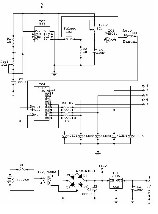
This circuit can be used for multiple cameras with one monitor. The circuit can be operated manually or automatically.
The described circuit functions as a video switching system, enabling the connection of multiple camera inputs to a single monitor output. This...

monitor splitter
The signal sources in the analog output stage of the PC SVGA card are designed to present the correct impedance of 75 ohms on each line, utilizing five resistors. The input impedances of the transistors are sufficiently high to avoid...

Camera power supply circuit
The camera power supply circuit illustrates the essential power supply required for the proper functioning of the camera. This power supply circuit is composed of a stable voltage control integrated circuit.
The camera power supply circuit is critical for ensuring that...

Basic Circuit Modification of Kodak Disposable Camera
The circuit diagram illustrates the original Kodak MAX Flash Unit, including the semiconductors that comprise the circuit. This diagram represents the unmodified version intended for the standard Kodak model, which should closely resemble the Kodak MAX model, if not identical....

lenovo e368 schematic
General use camera backlighting baseband circuit: the circuit includes a table of contents, Calyso, iota, matrix, keypad key, memory, IC image, LCD connector, LCD backlight driver, locate points, holes, Speaker4, camera connector, motor, MIDI/MP3 ICs, charging circuit, microphone phone, LDD...

Camera Head (A2075) Manual
The Camera Head (A2075) is a LWDAQ device designed to control and read a single ICX424 image sensor. The circuit includes a socket for soldering a 16-pin sensor directly and features a 12-way flex socket for connecting an auxiliary board...

10pin for cx700
This document outlines an update from 2011 to the 2008 LANC circuit project, referred to as Phase 2. The update enables the use of a CX700V camera within the same underwater video housing, known as a generic housing. Such housings...
Camera Switcher
This circuit can be utilized for multiple cameras with a single monitor. The operation can be manual or automatic. In automatic mode, the switch...
This circuit is designed to enable the connection of multiple cameras to a single monitor, allowing for...

panasonic wv f15 camera
Instructions for enabling the tally light on the F15 camera viewfinder without access to the CCU/RCU.
To activate the tally light on an F15 camera viewfinder in the absence of a Camera Control Unit (CCU) or Remote Control Unit (RCU), a...