


Water Level Indicator With 7-Segment Display PCB
#water level
#7-segment display
#buzzer
#liquid sensor
#overflow alert
#numeric display
#tank monitoring
#indicator circuit
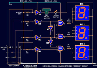
Description: Circuits designed to indicate water levels typically consist of LEDs to represent the liquid level. However, this circuit utilizes a 7-segment LED display instead of standard LEDs for a numeric representation of the water level. Additionally, a buzzer is incorporated to alert users when the tank is overflowing. The circuit displays "L," "H," and "F" for low, half, and full water levels, respectively. This circuit can be employed for water tank motor control or as a standalone device. The pins of the IC 7404 (NOT gate IC) are pulled high through a 1M ohm resistor, resulting in a low output voltage. As the tank fills with water, a low voltage is present at the input pins of the gate, causing it to output a high voltage. When the water level rises to touch the low-level sensor, pin 5 of gate N3 receives a low voltage, leading to a high output at pin 6. Since pin 6 of the gate is connected to pin 10 of gate N9, pin 10 also becomes high. Consequently, with both pins 9 and 10 of gate N9 high, its output pin 8 also goes high. This results in a positive supply being applied to DIS3, displaying "L" to indicate a low water level in the tank.
This water level indication circuit employs a 7-segment LED display for clear numeric representation, enhancing visibility compared to traditional LED indicators. The inclusion of a buzzer provides an auditory alert for overflow conditions, ensuring that users are promptly notified to prevent potential water spillage. The circuit operates based on the principles of digital logic using the 7404 NOT gate IC, which is configured to respond to varying input voltages corresponding to the water level.
The 1M ohm resistor serves a dual purpose: it pulls the gate input high under normal conditions and establishes a reference voltage level for the operation of the circuit. As water fills the tank, the conductive properties of the water engage the low-level sensor, which is strategically placed to trigger the necessary logic changes in the circuit. The cascading logic levels from the NOT gates effectively convert the analog water level into a digital signal that can be interpreted by the display.
The display outputs "L" when the water level is low, transitioning to "H" for half-full and "F" for full, allowing for easy monitoring of the tank's status. This design can be integrated into automated water tank systems where it can control the motor operation based on the water level readings, thereby enhancing efficiency and convenience. The circuit's modular design allows for adaptability in various applications, making it suitable for both residential and industrial water management systems.Circuits available for indicating water level is usually consist of LEDs to indicate the liquid level. But this circuit uses a 7-segment LED display instead of normal LED`s for numeric display of water level.
Moreover, a buzzer is used to alert you of water overflowing from the tank. The circuit shows the water level by displaying L, H and F for lo w, half and full, respectively. You can use this circuit for water tank motor control or a stand alone circuit. pins of IC 7404 (NOT gate IC) are pulled high via a 1M ohm resistor. So it outputs a low voltage. As water starts filling the tank, a low voltage is available at the input pins of the gate and it outputs a high voltage. When the water in the tank rises to touch the low level sensor, pin 5 of gate N3 gets a low voltage and results in high output at pin 6.
Pin 6 of the gate is connected to pin 10 of gate N9, so pin 10 also goes high. Now as both pins 9 and 10 of gate N9 are high, its output pin 8 also goes high. As a result, positive supply is applied to DIS3 and it shows L` indicating low level of water in the tank.
This water level indication circuit employs a 7-segment LED display for clear numeric representation, enhancing visibility compared to traditional LED indicators. The inclusion of a buzzer provides an auditory alert for overflow conditions, ensuring that users are promptly notified to prevent potential water spillage. The circuit operates based on the principles of digital logic using the 7404 NOT gate IC, which is configured to respond to varying input voltages corresponding to the water level.
The 1M ohm resistor serves a dual purpose: it pulls the gate input high under normal conditions and establishes a reference voltage level for the operation of the circuit. As water fills the tank, the conductive properties of the water engage the low-level sensor, which is strategically placed to trigger the necessary logic changes in the circuit. The cascading logic levels from the NOT gates effectively convert the analog water level into a digital signal that can be interpreted by the display.
The display outputs "L" when the water level is low, transitioning to "H" for half-full and "F" for full, allowing for easy monitoring of the tank's status. This design can be integrated into automated water tank systems where it can control the motor operation based on the water level readings, thereby enhancing efficiency and convenience. The circuit's modular design allows for adaptability in various applications, making it suitable for both residential and industrial water management systems.Circuits available for indicating water level is usually consist of LEDs to indicate the liquid level. But this circuit uses a 7-segment LED display instead of normal LED`s for numeric display of water level.
Moreover, a buzzer is used to alert you of water overflowing from the tank. The circuit shows the water level by displaying L, H and F for lo w, half and full, respectively. You can use this circuit for water tank motor control or a stand alone circuit. pins of IC 7404 (NOT gate IC) are pulled high via a 1M ohm resistor. So it outputs a low voltage. As water starts filling the tank, a low voltage is available at the input pins of the gate and it outputs a high voltage. When the water in the tank rises to touch the low level sensor, pin 5 of gate N3 gets a low voltage and results in high output at pin 6.
Pin 6 of the gate is connected to pin 10 of gate N9, so pin 10 also goes high. Now as both pins 9 and 10 of gate N9 are high, its output pin 8 also goes high. As a result, positive supply is applied to DIS3 and it shows L` indicating low level of water in the tank.
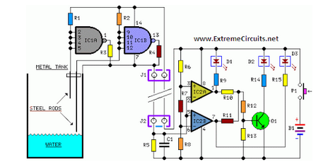
Water Level Indicator Circuit Schematic
Simple two-wire remote monitoring unit with a three-LED level display, powered by a 9V battery. The entire project was developed at the request of a friend.
The remote monitoring unit is designed to provide a straightforward solution for level indication in...

buzzer circuit diagram
The drive circuit is a basic drive recently designed to accommodate a 27mm passive piezoelectric buzzer, aiming for a sound output exceeding 100dB while minimizing power consumption. Due to constraints related to product cost and structural size, the circuit utilizes...

Oscillators for Buzzers and telephone Earpieces
In order to generate a single note you may try these simple circuits. With only three components you may implement some basic buzzers. You need a telephone earpiece for the first circuit. Any old telephone set has got one of...

Simple Buzzer Using Only Passive Components
This circuit is a simple buzzer circuit known as a novel buzzer. It utilizes a relay in series with a small audio transformer and a speaker. The relay will activate the circuit.
The novel buzzer circuit operates by employing a relay...

Water Level Alarm
A circuit that offers visual indication of fluid level in a vessel, with a switchable audible alarm. Example uses would be to monitor the level of water in a bath or cold storage tank.
The described circuit functions as a fluid...

7 segment rolling display using PC
It is very interesting and convenient to be able to control everything while sitting at your PC terminal. Here, a simple hardware circuit and software is used to interface a 7-segment based rolling display. The printer port of a PC...

Water Level Detector With Alarm
This is a simple alarm circuit that produces a musical tone when water or any conductive liquid comes into contact with the two sensor wires provided. The circuit utilizes four transistors and one melody generator IC (M3482). When water bridges...

7-segment displays tutorial LEDs sample circuits
A brief history: Like many tutorials, this one begins with a historical overview. However, it must be noted that there is limited background information available regarding the development of 7-segment displays.
7-segment displays are widely used electronic components that provide...
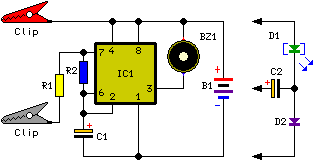
Water Level Alert
This circuit emits an intermittent beep or flashes an LED when the water level in a container reaches a specified height. It is designed to be mounted on top of the container, such as a plastic tank, using two crocodile...