


Wet soil tester with LED
#soil tester
#LED
#resistance
#transistor
#moisture detection
#probes
#simple circuit
#wet soil
#dry soil

Description: This is a very simple circuit that can be used to test whether a pot is dry or not. When the two probes are inserted in wet soil, then the resistance between the sensors are low. The base of T1 will therefore be more negative and the LED is not lit. However, when the soil is dry, its resistance will be high and will base more positive. Then the LED Ured with the two probes at a damp cloth held. P1 is then adjusted so that the LED just goes out.
P1 = 4.7 kOhm
D1 = LED
T1 = 547 BC
The circuit described operates as a moisture sensor that utilizes a simple transistor switch configuration to indicate the moisture level in soil or similar substrates. The two probes act as the sensing elements that detect the moisture content by measuring the resistance of the material between them.
When the probes are inserted into wet soil, the moisture provides a conductive path, resulting in low resistance. This low resistance condition causes the base of the NPN transistor (T1, 547 BC) to be at a lower potential, which keeps the transistor in the cutoff region. Consequently, the LED (D1) does not light up, indicating that the soil is sufficiently moist.
Conversely, when the soil dries out, the resistance between the probes increases significantly. This higher resistance leads to a more positive voltage at the base of the transistor, turning it on and allowing current to flow from the collector to the emitter. As a result, the LED lights up, providing a visual indication that the soil is dry.
The potentiometer (P1, 4.7 kOhm) is used to calibrate the sensitivity of the circuit. By adjusting P1, the threshold at which the LED turns on or off can be fine-tuned based on the specific moisture levels desired. This adjustment is crucial for ensuring accurate readings, particularly in varying soil types or conditions.
The circuit's simplicity makes it an effective solution for gardeners and horticulturists looking to monitor soil moisture without the need for complex electronic components. The use of a standard transistor and LED allows for easy assembly and minimal power consumption, making it suitable for battery-operated applications.This is a very simple circuit that can be used to test whether a pot is dry or not. When the two probes are inserted in wet soil, then the resistance between the sensors are low. The base of T1 will therefore be more negative and the LED is not lit. However, when the soil is dry, its resistance will be high and will base more positive. Then the LED Ured with the two probes at a damp cloth held. P1 is then adjusted so that the LED just goes out. P1 = 4.7 kOhm D1 = LED T1 = 547 BC
P1 = 4.7 kOhm
D1 = LED
T1 = 547 BC
The circuit described operates as a moisture sensor that utilizes a simple transistor switch configuration to indicate the moisture level in soil or similar substrates. The two probes act as the sensing elements that detect the moisture content by measuring the resistance of the material between them.
When the probes are inserted into wet soil, the moisture provides a conductive path, resulting in low resistance. This low resistance condition causes the base of the NPN transistor (T1, 547 BC) to be at a lower potential, which keeps the transistor in the cutoff region. Consequently, the LED (D1) does not light up, indicating that the soil is sufficiently moist.
Conversely, when the soil dries out, the resistance between the probes increases significantly. This higher resistance leads to a more positive voltage at the base of the transistor, turning it on and allowing current to flow from the collector to the emitter. As a result, the LED lights up, providing a visual indication that the soil is dry.
The potentiometer (P1, 4.7 kOhm) is used to calibrate the sensitivity of the circuit. By adjusting P1, the threshold at which the LED turns on or off can be fine-tuned based on the specific moisture levels desired. This adjustment is crucial for ensuring accurate readings, particularly in varying soil types or conditions.
The circuit's simplicity makes it an effective solution for gardeners and horticulturists looking to monitor soil moisture without the need for complex electronic components. The use of a standard transistor and LED allows for easy assembly and minimal power consumption, making it suitable for battery-operated applications.This is a very simple circuit that can be used to test whether a pot is dry or not. When the two probes are inserted in wet soil, then the resistance between the sensors are low. The base of T1 will therefore be more negative and the LED is not lit. However, when the soil is dry, its resistance will be high and will base more positive. Then the LED Ured with the two probes at a damp cloth held. P1 is then adjusted so that the LED just goes out. P1 = 4.7 kOhm D1 = LED T1 = 547 BC

how to make 18 led light chaser circuit
Decorative lights arranged in various moving patterns are visually appealing and have gained significant popularity in today's world. While more complex lighting arrangements may require the use of microcontroller ICs, simpler yet captivating light effects can be generated using ordinary...

transistors Role of capacitor in this circuit
Oscillation is expected at the resonant frequency where the positive feedback is in phase with the input, specifically at 0 degrees. For oscillation to take place, the gain must be equal to or greater than 1 at that frequency. There...
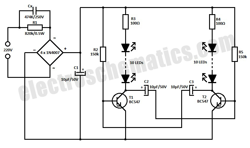
220V LED Blinker Circuit
This is a simple LED blinker or flasher designed for decorative purposes. The circuit features 20 high-brightness LEDs that flash alternately, creating a vibrant color display.
The LED blinker circuit typically consists of several key components including a microcontroller or timer...

220 V LED Night light
This is a capacitor power supply. This is a very small current of energy-effective because it has very little loss, much smaller than the miniature transformer. Capacitor impedance is inversely proportional to frequency. This is a great disadvantage when the...
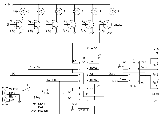
KIT CAR Lights circuit
This custom mod gives your computer the personality of KITT, the computerized car from Knight Rider TV fame. The project is a light display which imitates the dot in KITT's hood. It looks like the scanning eye of the car's...

Electronic-bird-chirper
Transistors Q1 and Q2 form the two halves of a free-running multivibrator, with the frequency determined by the voltage across capacitor C8. This capacitor is charged and discharged by the operation of switch S1. Transistors Q3 and Q4 constitute a...

simple led torch circuit
This circuit is a simple LED torch utilizing the MAX660 integrated circuit from MAXIM semiconductors. The MAX660 is a CMOS monolithic voltage converter IC capable of driving three bright white LEDs connected in parallel to output pin 8 of the...

Three of the five band equalizer circuit transistor
Figure 4-33 illustrates a circuit configuration that includes a common amplifier along with analog inductive circuits. In this setup, the transistor in the analog inductive circuit is utilized, and an increase in the bias resistor enhances circuit stability. A potentiometer...

Bicolour LED flasher circuit
This circuit is similar to various published flasher circuits that utilize the IC 555 as a free-running multivibrator. The primary distinction is in the method of flashing bi-color LEDs. When the output at pin 3 of the IC 555 goes...