


wind meters

Description: This circuit diagram represents a simple wind meter. The working principle involves transistors Q1 and Q2, which are used to sense the wind. The relationship between thermal impedance and the surrounding transistors determines the wind speed. The collector-emitter voltage (VCE) of Q1 is higher than that of Q2, resulting in increased power dissipation. The wind causes cooling, which alters the VCE of Q1, leading to different power dissipations that are detected by resistor R10. This voltage is then amplified by an operational amplifier to generate an output voltage (Fout) that corresponds to the wind speed. When there is no air movement, Fout is 0V, and at a wind speed of 75 m/s, Fout reaches 2.5V. A voltmeter with a full-scale deflection (FSD) of 3V is connected across the output and ground, serving as a display. The circuit requires a 5V DC power supply. For proper operation, air must flow through both transistors (Q1 and Q2). Most resistors used in the circuit are standard values, so it may be necessary to combine resistors in series or parallel to achieve specific resistance values. It is crucial to note that the resistor values are very important in this circuit.
The wind meter circuit operates on the principle of differential thermal response between two transistors. Transistors Q1 and Q2 are positioned to have their junctions exposed to the airflow. As the wind flows over these transistors, it cools them, leading to variations in their VCE based on the wind speed. The differential power dissipation between the two transistors is a key factor in determining the output voltage.
The operational amplifier serves to amplify the small voltage differences detected by R10, which is critical for providing a readable output. The output voltage (Fout) is linearly related to the wind speed, allowing for easy interpretation. The scaling of the output voltage to correspond with wind speed can be adjusted by changing the gain of the operational amplifier or by modifying the resistor values in the feedback loop.
It is essential to ensure that the transistors are selected based on their thermal characteristics and response times, as these parameters can significantly affect the accuracy and responsiveness of the wind meter. Additionally, the circuit's power supply must be stable and provide a constant 5V to ensure reliable operation.
Careful consideration must be given to the resistor values used in the circuit. They must be chosen to optimize the sensitivity and range of the wind meter. Using a potentiometer in conjunction with fixed resistors may provide a means to calibrate the device for specific applications or environmental conditions.
The schematic diagram accompanying this description would illustrate the arrangement of the components, including the transistors, resistors, operational amplifier, and the connection to the voltmeter, providing a clear visual representation of the circuit's functionality.This circuit is a circuit diagram gauges simple wind meter. Working principle of this circuit are the transistors Q1 and Q2 are used to feel the wind. The relationship between thermal impedance and the surrounding transistors utilized wind speed here. Transistors Q1 and Q2 is the cable that VCE of Q1 is higher than Q2 and therefore power dissipati on will be higher. The wind causes the cooling so that Q1 VCE of changes. Which ended at different power dissipations and the different variations detected by R10. This voltage opamp and strengthened to generate comparable Fout wind speed. To air is still Fout will 0V and at 75 m / s wind speed will Fout 2. 5V. A voltmeter FSD Fout 3V is connected across the terminal and ground can be used as a screen. The following is a schematic drawing: The circuit requires 5V DC voltage. To work properly, the air must pass through two transistors (Q1 and Q2). Most of the resistors are not used here are the standard values. So, you should use a combination (series or parallel) resistors to achieve certain values. Please note that the resistor values is very important in this circuit.
The wind meter circuit operates on the principle of differential thermal response between two transistors. Transistors Q1 and Q2 are positioned to have their junctions exposed to the airflow. As the wind flows over these transistors, it cools them, leading to variations in their VCE based on the wind speed. The differential power dissipation between the two transistors is a key factor in determining the output voltage.
The operational amplifier serves to amplify the small voltage differences detected by R10, which is critical for providing a readable output. The output voltage (Fout) is linearly related to the wind speed, allowing for easy interpretation. The scaling of the output voltage to correspond with wind speed can be adjusted by changing the gain of the operational amplifier or by modifying the resistor values in the feedback loop.
It is essential to ensure that the transistors are selected based on their thermal characteristics and response times, as these parameters can significantly affect the accuracy and responsiveness of the wind meter. Additionally, the circuit's power supply must be stable and provide a constant 5V to ensure reliable operation.
Careful consideration must be given to the resistor values used in the circuit. They must be chosen to optimize the sensitivity and range of the wind meter. Using a potentiometer in conjunction with fixed resistors may provide a means to calibrate the device for specific applications or environmental conditions.
The schematic diagram accompanying this description would illustrate the arrangement of the components, including the transistors, resistors, operational amplifier, and the connection to the voltmeter, providing a clear visual representation of the circuit's functionality.This circuit is a circuit diagram gauges simple wind meter. Working principle of this circuit are the transistors Q1 and Q2 are used to feel the wind. The relationship between thermal impedance and the surrounding transistors utilized wind speed here. Transistors Q1 and Q2 is the cable that VCE of Q1 is higher than Q2 and therefore power dissipati on will be higher. The wind causes the cooling so that Q1 VCE of changes. Which ended at different power dissipations and the different variations detected by R10. This voltage opamp and strengthened to generate comparable Fout wind speed. To air is still Fout will 0V and at 75 m / s wind speed will Fout 2. 5V. A voltmeter FSD Fout 3V is connected across the terminal and ground can be used as a screen. The following is a schematic drawing: The circuit requires 5V DC voltage. To work properly, the air must pass through two transistors (Q1 and Q2). Most of the resistors are not used here are the standard values. So, you should use a combination (series or parallel) resistors to achieve certain values. Please note that the resistor values is very important in this circuit.

Transistor Geiger Counter
One of the most unfortunate features of the typical portable Geiger counter is the short lifespan of the costly high-voltage batteries.
The limitation of high-voltage battery life in portable Geiger counters significantly affects their usability and operational efficiency. These devices are...

transistor astable multivibrator
Assume one of the transistors, TR1, becomes conductive initially. Under this condition, the collector-emitter voltage of TR1 should ideally be zero; however, it will be approximately 0.1 volts, while the base-emitter voltage is +0.6 volts. As a result, capacitor C1...
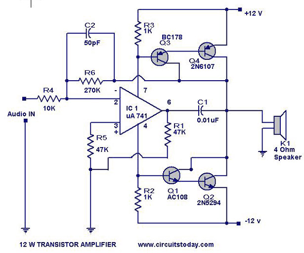
Transistor Amplifier Circuit with Diagram for 12 Watts
A simple transistor amplifier circuit diagram and schematic that can be used as a 12-watt audio transistor amplifier. An operational amplifier (op-amp) integrated circuit (IC) is used to produce the required gain.
This circuit is designed to amplify audio signals, making...

A circuit diagram of the filter by the transistor
This article describes a band-pass filter circuit diagram utilizing transistors.
A band-pass filter is an essential electronic circuit that allows signals within a certain frequency range to pass while attenuating frequencies outside that range. The circuit typically consists of a combination...
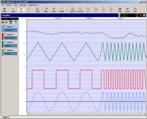
RealView 2.0
RealView is a measurement application, which records and plots measured values from analogue hardware devices in real-time. Several curves can be plotted into a single diagram. Several diagrams can be arranged on one or more pages if necessary. Plot options...

improved 3 transistor audio amp
This circuit is similar to the previous one but employs positive feedback to enhance the amplitude delivered to the speaker. It is adapted from a small 5-transistor radio that utilizes a 25-ohm speaker. In the earlier circuit, the load resistor...

Full on transistor/fet curve tracer
The project involves adapting a curve tracer schematic, likely based on Metzger's circuit from the early 1970s, to integrate an ADC capture system and output the data to a 320x256 ELD panel. Additionally, a serial output will be included to...

audio tone control 2 transistor circuit
The first BC109C transistor functions as a buffer, delivering a high input impedance of approximately 250k and exhibiting a voltage gain marginally below unity. Given that the Baxendall tone control circuit operates passively, it attenuates all audio frequencies. The audio...

Motor vehicle steering flasher 12
The motor vehicle steering flasher described in the example utilizes high-power transistors as electronic switches, and the circuit is simple and easy to construct. The motor vehicle steering flasher consists of the flash circuit with resistors R1-R3, a capacitor C,...