


AC triggered switch
#AC triggered
#transistor
#common emitter
#voltage operated
#discrete components
#low frequency
#switch
#biasing
#load control

Description: An AC triggered switch for low frequency signals. This is a basic ac voltage operated switch made from discrete components. Both Q1 and Q2 work as common emitter amplifiers, but the biasing of Q1 is arranged by R3 and R4 so that about 0.5V is applied to its base; so with no input signal both transistors and the load is off. More: With an input signal greater than 0.3V pk-pk (100mV RMS) the positive half of the waveform will switch on Q1, and Q2 and the relay. As the input signal switches to its negative transition, Q1 will switch off, but base current in Q2 continues to flow via C.
The described circuit functions as an AC-triggered switch designed for low-frequency signal applications. It employs two transistors, Q1 and Q2, configured as common emitter amplifiers, which are pivotal in controlling the flow of current to the load, represented by a relay.
Transistor Q1 is biased through resistors R3 and R4, establishing a base voltage of approximately 0.5V. This biasing is crucial as it ensures that in the absence of an input signal, both transistors remain in the off state, thus preventing any current flow through the load. The circuit is designed to respond to input signals above a threshold of 0.3V peak-to-peak (equivalent to 100mV RMS).
When an input signal exceeds this threshold, the positive half-cycle of the AC waveform activates Q1, allowing current to flow through Q2, which subsequently energizes the relay. This action effectively closes the circuit, enabling power to the load. As the input signal transitions into its negative half-cycle, Q1 turns off, but Q2 continues to conduct due to the base current flowing through capacitor C. This behavior ensures that the relay remains activated for the duration of the positive half-cycle, providing a stable output despite the AC signal's fluctuations.
The overall design is characterized by its simplicity and reliance on discrete components, making it a cost-effective solution for applications requiring reliable switching mechanisms in response to low-frequency AC signals. The careful selection of component values, particularly the biasing resistors and the capacitor, is essential for optimizing the circuit's performance and responsiveness to input signals.An AC triggered switch for low frequency signals. This is a basic ac voltage operated switch made from discrete components. Both Q1 and Q2 work as common emitter amplifiers, but the biasing of Q1 is arranged by R3 and R4 so that about 0.5V is applied to its base; so with no input signal both transistors and the load is off. With an input signal greater than 0.3V pk-pk (100mV RMS) the positive half of the waveform will switch on Q1, and Q2 and the relay. As the input signal switches to its negative transition, Q1 will switch off, but base current in Q2 continues to flow via C
The described circuit functions as an AC-triggered switch designed for low-frequency signal applications. It employs two transistors, Q1 and Q2, configured as common emitter amplifiers, which are pivotal in controlling the flow of current to the load, represented by a relay.
Transistor Q1 is biased through resistors R3 and R4, establishing a base voltage of approximately 0.5V. This biasing is crucial as it ensures that in the absence of an input signal, both transistors remain in the off state, thus preventing any current flow through the load. The circuit is designed to respond to input signals above a threshold of 0.3V peak-to-peak (equivalent to 100mV RMS).
When an input signal exceeds this threshold, the positive half-cycle of the AC waveform activates Q1, allowing current to flow through Q2, which subsequently energizes the relay. This action effectively closes the circuit, enabling power to the load. As the input signal transitions into its negative half-cycle, Q1 turns off, but Q2 continues to conduct due to the base current flowing through capacitor C. This behavior ensures that the relay remains activated for the duration of the positive half-cycle, providing a stable output despite the AC signal's fluctuations.
The overall design is characterized by its simplicity and reliance on discrete components, making it a cost-effective solution for applications requiring reliable switching mechanisms in response to low-frequency AC signals. The careful selection of component values, particularly the biasing resistors and the capacitor, is essential for optimizing the circuit's performance and responsiveness to input signals.An AC triggered switch for low frequency signals. This is a basic ac voltage operated switch made from discrete components. Both Q1 and Q2 work as common emitter amplifiers, but the biasing of Q1 is arranged by R3 and R4 so that about 0.5V is applied to its base; so with no input signal both transistors and the load is off. With an input signal greater than 0.3V pk-pk (100mV RMS) the positive half of the waveform will switch on Q1, and Q2 and the relay. As the input signal switches to its negative transition, Q1 will switch off, but base current in Q2 continues to flow via C
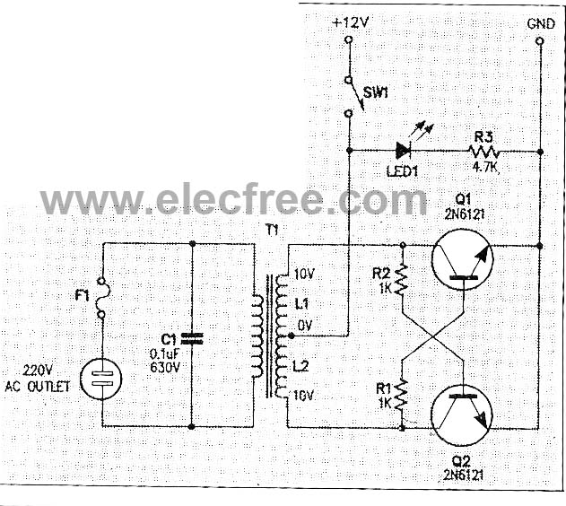
Micro Inverter by 2N6121
This micro inverter is a small-sized device that modifies energy from a battery, producing an output voltage of approximately 220V AC at 50Hz. The circuit comprises two transistors that function as a pulse oscillator or square wave generator, driving a...
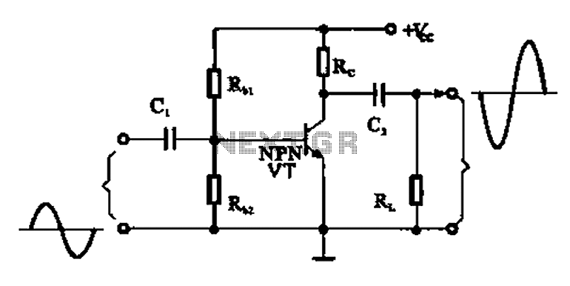
A common emitter amplifier
A common emitter amplifier is a total pole amplification circuit structure featuring a key emitting device. This circuit refers to the emitter of the input signal and the output signal connected to a common ground, forming the basis of fundamental...

darklight sensor using transistor
An automatic dark detector senses darkness. As the light level decreases and the light-dependent resistor (LDR) reaches the maximum threshold resistance, the circuit automatically activates the LED D1. Conversely, a light detector senses light, and when the light level increases...

Transistor Organ
This simple circuit can provide hours of enjoyment as you learn tunes, play duets or just make some really weird sounds by pushing all the buttons at once. You have probably seen this circuit before, it is fairly common. I...

Motor time division control circuit composed of transistor and NE555
Figure 2-32 (a) illustrates the time control diagram for a motor operated by switch S1. When S1 is set to position 1, the power driver circuit supplies current to the motor, enabling it to run. When S1 is switched to...

Mini Tracker
A grasshopper is a switch that can activate at any moment. A plastic piece is positioned between two switch contacts to keep them apart, connected to a cotton thread fixed to the floor. When the object is moved, the cotton...

Two-Transistor DC Motor DriverCircuit Using The TIP32 Transistor
The following circuit illustrates a two-transistor DC motor driver circuit diagram. This circuit utilizes the TIP32 transistor. Features: operates in...
The two-transistor DC motor driver circuit is designed to control the operation of a DC motor using two NPN transistors, which...

water activated alarm
Under dry conditions, the transistor will not have any bias current and will be completely off. However, when the probes become wet, the transistor will conduct, triggering the alarm. An On/Off switch is included, and it is important to use...
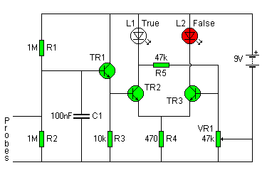
lie detector
The circuit diagram of the Lie Detector consists of three transistors (TR1 to TR3), a capacitor (C1), two LEDs (L1 & L2), five resistors (R1 to R5), and a variable resistor (VR1). Suitable transistors include BC547, BC548, or BC549, or...