


auto changeover from generator to mains
#auto changeover
#generator
#mains supply
#power switching
#load shedding
#voltage protection
#household appliances
#energy crisis
#power fluctuations
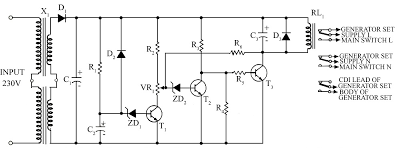
Description: Due to the energy crisis, load shedding has become a common issue in several countries. Sudden power fluctuations, surges, and high voltage can damage sensitive household appliances such as TVs, VCRs, VCPs, and music systems. This circuit offers protection against these problems by automatically switching the power supply from the generator output to the mains supply and also turning off the generator. The circuit is self-explanatory. When the line supply voltage exceeds the preset level, Zener diode ZD4 breaks down, causing transistor T2 to conduct while transistor T3 does not, which de-energizes the relay. A delay circuit around transistor T1 protects against voltage surges upon power resumption. All portable petrol and kerosene generators have a connection from the CDI. To stop the generator engine, this connection must be grounded momentarily (via a switch). This lead is connected to ground through the normally closed (N/C) point of the relay. Instead of a single transformer, two transformers are used in series to enhance the unit's lifespan. The value of capacitor C2 can be adjusted to vary the delay time. A negative feedback resistor, R6 (ranging from 15 k-ohm to 100 k-ohm), can be added between transistors T3 and T4 to mitigate damage from voltage fluctuations.
The circuit designed for protecting household appliances from power fluctuations and surges incorporates several key components that work together to ensure safe operation. The primary function of this circuit is to monitor the incoming line voltage and respond accordingly when it exceeds a predetermined threshold. This is accomplished using a Zener diode (ZD4), which is configured to break down at a specific voltage level. When the voltage crosses this threshold, ZD4 conducts, triggering transistor T2 to enter a conductive state. This action effectively turns off transistor T3, leading to the de-energization of the relay that controls the connection to the mains supply.
In addition to the immediate response to over-voltage conditions, the circuit includes a delay mechanism implemented around transistor T1. This delay serves to protect the connected appliances from potential voltage surges that may occur when power is restored after a blackout or load shedding event. The delay can be adjusted by varying the capacitance of capacitor C2, allowing for customization based on the specific requirements of the connected appliances and the characteristics of the power supply.
The circuit also integrates a safety feature for generator operation. Portable generators, whether powered by petrol or kerosene, typically have a connection from the CDI (Capacitor Discharge Ignition) system. To safely stop the generator engine, this connection must be momentarily grounded, which is facilitated through a switch connected to the normally closed point of the relay. This ensures that the generator can be turned off safely without risking damage to the system.
To enhance the reliability and longevity of the circuit, two transformers are employed in series rather than a single transformer. This configuration helps distribute the load more effectively, reducing wear and tear on individual components. Additionally, a negative feedback resistor (R6) can be incorporated between transistors T3 and T4. This resistor, with a resistance value adjustable between 15 k-ohm and 100 k-ohm, helps to stabilize the circuit and prevent potential damage from voltage fluctuations, thereby ensuring consistent performance over time.
Overall, this circuit provides a robust solution for protecting sensitive electronic equipment from the adverse effects of power supply irregularities while also ensuring safe generator operation.Because of energy crisis Load shedding may be a common problem in several countries. Sudden power fluctuations, surge and high voltage may spoil sophisticated household appliances like TV, VCR, VCP and music system. This circuit provides protection against these problems and automatically changes the power supply from Generator output to mains sup
ply and also switches off the generator. This circuit is self explanatory. When lines supply voltage crosses the preset level, Zener diode ZD4 break down and thus transistor T2 conducts, T3 does not conduct, causing the relay to de-energise. Voltage surge at the time of power resumption is protected by the delay circuit around transistor T1.
All the portable petrol and kerosene generators have a connection from CDI. To stop the engine of the generator-set, this connection is to be grounded momentarily (through the switch). This lead is to be connected with the ground through the N/C point of the relay. Instead of the one transformer, two transformers are used in series to ensure better life of the unit.
Value of capacitor C2 can be increased or decreased for the variation of delay time. A negative feedback resistance, R6 (15 K-ohm to 100 k-ohm) can be incorporated between transistor T3 and T4 to overcome the damage that could be caused by voltage fluctuations.
The circuit designed for protecting household appliances from power fluctuations and surges incorporates several key components that work together to ensure safe operation. The primary function of this circuit is to monitor the incoming line voltage and respond accordingly when it exceeds a predetermined threshold. This is accomplished using a Zener diode (ZD4), which is configured to break down at a specific voltage level. When the voltage crosses this threshold, ZD4 conducts, triggering transistor T2 to enter a conductive state. This action effectively turns off transistor T3, leading to the de-energization of the relay that controls the connection to the mains supply.
In addition to the immediate response to over-voltage conditions, the circuit includes a delay mechanism implemented around transistor T1. This delay serves to protect the connected appliances from potential voltage surges that may occur when power is restored after a blackout or load shedding event. The delay can be adjusted by varying the capacitance of capacitor C2, allowing for customization based on the specific requirements of the connected appliances and the characteristics of the power supply.
The circuit also integrates a safety feature for generator operation. Portable generators, whether powered by petrol or kerosene, typically have a connection from the CDI (Capacitor Discharge Ignition) system. To safely stop the generator engine, this connection must be momentarily grounded, which is facilitated through a switch connected to the normally closed point of the relay. This ensures that the generator can be turned off safely without risking damage to the system.
To enhance the reliability and longevity of the circuit, two transformers are employed in series rather than a single transformer. This configuration helps distribute the load more effectively, reducing wear and tear on individual components. Additionally, a negative feedback resistor (R6) can be incorporated between transistors T3 and T4. This resistor, with a resistance value adjustable between 15 k-ohm and 100 k-ohm, helps to stabilize the circuit and prevent potential damage from voltage fluctuations, thereby ensuring consistent performance over time.
Overall, this circuit provides a robust solution for protecting sensitive electronic equipment from the adverse effects of power supply irregularities while also ensuring safe generator operation.Because of energy crisis Load shedding may be a common problem in several countries. Sudden power fluctuations, surge and high voltage may spoil sophisticated household appliances like TV, VCR, VCP and music system. This circuit provides protection against these problems and automatically changes the power supply from Generator output to mains sup
ply and also switches off the generator. This circuit is self explanatory. When lines supply voltage crosses the preset level, Zener diode ZD4 break down and thus transistor T2 conducts, T3 does not conduct, causing the relay to de-energise. Voltage surge at the time of power resumption is protected by the delay circuit around transistor T1.
All the portable petrol and kerosene generators have a connection from CDI. To stop the engine of the generator-set, this connection is to be grounded momentarily (through the switch). This lead is to be connected with the ground through the N/C point of the relay. Instead of the one transformer, two transformers are used in series to ensure better life of the unit.
Value of capacitor C2 can be increased or decreased for the variation of delay time. A negative feedback resistance, R6 (15 K-ohm to 100 k-ohm) can be incorporated between transistor T3 and T4 to overcome the damage that could be caused by voltage fluctuations.

A small generator and network control circuit
Circle i represents a two-phase grid connection line for an AC technology turbine shed, which consists of two lines. A voltage is generated between Ri through a Buck converter, with components R1 and R3 dividing the output. The sampled level...

high and low voltage cut out with delay and music circuit diagram
Voltage variations and power cuts adversely affect various equipment such as TVs, VCRs, music systems, and refrigerators. This simple circuit will protect costly equipment from high and low voltages and voltage surges when power resumes. It also produces a melodious...

Self runner Generator
The timing must be exact to get those high voltage spikes. I used a tiny magnet on the rotor, that triggered a reed switch allowing the relay to pulse the energy from the recovery coil to the primary battery. In...

Zero sequence voltage phase protection circuit 2
A potentiometer (RP) is utilized for adjusting the operating voltage of the relay (KA) to ensure that the motor operates normally, especially when the relay (KA) does not function reliably during the action phase.
The circuit involves a potentiometer connected...

Power-switching circuit
This circuit facilitates on/off switching, soft starting, current monitoring, current tripping, and overcurrent protection for a 30 Vdc power supply, accommodating normal load currents of up to 2 A. The switch is activated by an "on" command pulse and deactivated...

300 to 1500kW straight with a generator of Lightning
300 to 1500 kW direct distribution lightning generator designed for single capacities ranging from 300 kW to 1500 kW.
The lightning generator operates within a power range of 300 kW to 1500 kW, providing a direct distribution system that facilitates the...

Automatic generator start battery monitor circuit diagram
As shown in the generator start battery automatic monitor circuit diagram.
The generator start battery automatic monitor circuit is designed to oversee the battery's status during generator operation. This circuit ensures that the battery remains charged and functional, preventing premature failure...

High And Low Voltage Cut Off With Time Delay
Power line fluctuations and cut-offs can damage electrical appliances connected to the line, particularly domestic appliances like refrigerators and air conditioners. When a refrigerator operates on low voltage, excessive current flows through the motor, leading to overheating and potential damage....
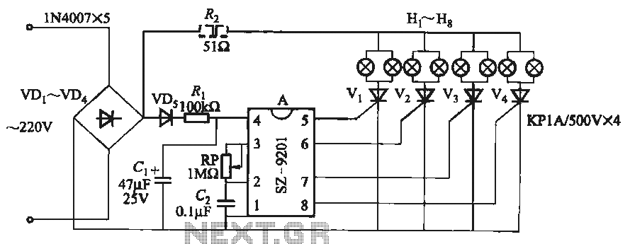
SZ-9201 uses three function lights chain circuit
It utilizes the mains supply through a basic DC rectifier circuit.
The circuit operates by converting alternating current (AC) from the mains supply into direct current (DC) using a rectifier. A typical implementation involves a bridge rectifier configuration, which consists of...