


Compact Switching Step-Down Converter By MAX639
#step-down converter
#switch-mode
#power supply
#voltage regulation
#MAX639
#efficiency
#compact design
#DC-DC converter

Description: Switch-mode power supplies are utilized in electronic circuits to efficiently increase (step up) or decrease (step down) voltage levels. In comparison to linear voltage regulators, switch-mode supplies convert minimal energy into heat, resulting in high efficiency. This characteristic is particularly advantageous for compact power supplies, as it can eliminate the need for forced-air cooling. Constructing a switch-mode supply is significantly easier with components specifically designed for this purpose. An example of such an integrated step-down converter is the Maxim MAX639, which is engineered for a fixed output voltage of +5V, with an input voltage range of +5.5V to +11.5V. Although this integrated circuit (IC) is primarily intended for a fixed output voltage, the output voltage can be adjusted using a straightforward feedback network. The output voltage is determined by the values of resistors R3 and R4, following the equation R3 = R4 [(Vout / 1.28) - 1]. The value of R4 can range from 10k to 10M, with 100k being a suitable choice for most applications. The maximum output current is 100mA. If desired, a different Schottky diode with similar specifications can be used in place of D1 (1N5817). Inductor L1 must be rated for a maximum current of 500mA.
Switch-mode power supplies (SMPS) are pivotal in modern electronic circuit design due to their ability to efficiently manage voltage levels. These supplies utilize high-frequency switching techniques to regulate output voltage while minimizing energy loss. The Maxim MAX639 integrated circuit serves as an exemplary step-down converter, providing a stable +5V output from a variable input voltage between +5.5V and +11.5V. This IC is particularly advantageous in applications where space and thermal management are critical.
The design of the MAX639 allows for output voltage adjustment through a feedback network, which consists of resistors R3 and R4. By selecting appropriate values for these resistors, the output voltage can be fine-tuned to meet specific requirements. The formula R3 = R4 [(Vout / 1.28) - 1] facilitates this adjustment, enabling designers to achieve desired voltage levels with precision. The recommended value of 100k for R4 balances performance and flexibility, accommodating a range of applications.
The output current specification of 100mA ensures that the MAX639 can adequately power various loads, while the capability to substitute the Schottky diode (D1) with other compatible types allows for design flexibility. The choice of inductor L1 is also critical, as it must handle a maximum current of 500mA to prevent saturation and ensure reliable operation. This consideration is vital in maintaining the efficiency and longevity of the power supply.
In summary, the integration of the MAX639 in a switch-mode power supply design exemplifies the advantages of using specialized components in achieving efficient voltage regulation. The combination of high efficiency, adjustable output voltage, and compact design makes SMPS an essential element in contemporary electronic systems.Switch-mode power supplies are used in electronic circuits to increase (step up) or reduce (step down) voltage levels in the most efficient manner possible. Compared to linear voltage regulators, switch-mode supplies convert relatively little energy into heat.
Their efficiency is thus high. This is a major advantage with compact power supplies in particular, since it sometimes makes forced-air cooling unnecessary. Building a switch-mode supply is considerably easier if you use components that have been specially developed for this application. One example of such an integrated step-down converter is the Maxim MAX639. This is designed for axed output voltage of +5V, with an input voltage ranging between +5. 5 and +11. 5V. Although this IC is primarily designed for axed output voltage, the output voltage can be tailored using a simple feedback network.
With the given component values, resistors R3 and R4 determine the output voltage, with R3 = R4 [(Vout / 1. 28) 1] The value of R4 may lie between 10k and 10M, but a value of 100 k is a good choice for most applications.
The maximum output current is 100mA. If desired, a different type of Schottky diode with similar specifications can be used in place of D1 (a 1N5817). Inductor L1 must be suitable for a maximum current of 500mA.
Switch-mode power supplies (SMPS) are pivotal in modern electronic circuit design due to their ability to efficiently manage voltage levels. These supplies utilize high-frequency switching techniques to regulate output voltage while minimizing energy loss. The Maxim MAX639 integrated circuit serves as an exemplary step-down converter, providing a stable +5V output from a variable input voltage between +5.5V and +11.5V. This IC is particularly advantageous in applications where space and thermal management are critical.
The design of the MAX639 allows for output voltage adjustment through a feedback network, which consists of resistors R3 and R4. By selecting appropriate values for these resistors, the output voltage can be fine-tuned to meet specific requirements. The formula R3 = R4 [(Vout / 1.28) - 1] facilitates this adjustment, enabling designers to achieve desired voltage levels with precision. The recommended value of 100k for R4 balances performance and flexibility, accommodating a range of applications.
The output current specification of 100mA ensures that the MAX639 can adequately power various loads, while the capability to substitute the Schottky diode (D1) with other compatible types allows for design flexibility. The choice of inductor L1 is also critical, as it must handle a maximum current of 500mA to prevent saturation and ensure reliable operation. This consideration is vital in maintaining the efficiency and longevity of the power supply.
In summary, the integration of the MAX639 in a switch-mode power supply design exemplifies the advantages of using specialized components in achieving efficient voltage regulation. The combination of high efficiency, adjustable output voltage, and compact design makes SMPS an essential element in contemporary electronic systems.Switch-mode power supplies are used in electronic circuits to increase (step up) or reduce (step down) voltage levels in the most efficient manner possible. Compared to linear voltage regulators, switch-mode supplies convert relatively little energy into heat.
Their efficiency is thus high. This is a major advantage with compact power supplies in particular, since it sometimes makes forced-air cooling unnecessary. Building a switch-mode supply is considerably easier if you use components that have been specially developed for this application. One example of such an integrated step-down converter is the Maxim MAX639. This is designed for axed output voltage of +5V, with an input voltage ranging between +5. 5 and +11. 5V. Although this IC is primarily designed for axed output voltage, the output voltage can be tailored using a simple feedback network.
With the given component values, resistors R3 and R4 determine the output voltage, with R3 = R4 [(Vout / 1. 28) 1] The value of R4 may lie between 10k and 10M, but a value of 100 k is a good choice for most applications.
The maximum output current is 100mA. If desired, a different type of Schottky diode with similar specifications can be used in place of D1 (a 1N5817). Inductor L1 must be suitable for a maximum current of 500mA.

Panasonic M12H switching power supply circuit diagram
The Panasonic M12H switching power supply circuit is utilized in Panasonic models such as TC-230H, TC-2030DHN, TC-830D, and TC-840D. The circuit operates with an oscillation frequency that generates approximately 300V DC voltage at C836. The T801 transformer is involved in...

The many DC to DC converters using IC-555
This is a simple voltage doubler circuit that converts 12V DC into 24V DC. It utilizes the popular NE555 timer IC along with a few additional components. The circuit can provide approximately 50mA of current, making it suitable for low-current...

35W switching power supply circuit having a set-top box output of 5
A 35W switching power supply circuit designed for a set-top box output is depicted in Figure 5. It features five distinct voltage outputs: Uo1 (+30V, 100mA), Uo2 (+18V, 550mA), Uo3 (+5V, 2.5A), Uo4 (+3.3V, 3A), and Uo5 (-5V, 100mA). The...

Isolated 15 to 1000V DC-DC Converter
The circuit illustrated in the schematic diagram below is an isolated DC-to-DC step-up converter. The term "isolated" indicates that there is no electrical connection between the input and output sections of the circuit.
The isolated DC-to-DC step-up converter operates by converting...

Designing Multiple Output Power Supplies With Topswitch
This application note describes a digital blood pressure meter concept that utilizes integrated pressure sensor analog signal-conditioning circuitry, microcontroller hardware/software, and a liquid crystal display. The sensing system measures cuff pressure (CP) and extracts pulses for analysis to determine systolic...

Switching power supply monolithic switching regulator DN-25 configuration
As shown in the figure, the DN-25 IC is a switching power supply. The DN-25 is a monolithic switching power supply device suitable for medium output current applications and a wide voltage range. Its main performance indicators include an input...

6V to15V DC to DC converter using LM2585 wired in the boost mode
A simple and efficient 6 to 15V boost/step-up DC to DC converter based on IC L2585. This voltage converter circuit requires few external components.
The circuit utilizes the L2585 integrated circuit, which is designed for high-efficiency voltage boosting applications. The L2585...
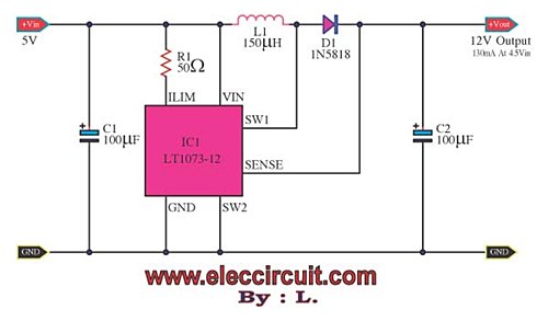
The most DC to DC converter step up voltage by LT1073
Suppose there is a need to utilize a 5V DC power supply capable of delivering up to 100mA, but only a single AA 1.5V battery is available. To achieve this, a DC to DC converter must be employed.
To convert the...

100v / 10ma regulator circuit
The circuit features no-load and short circuit protection mechanisms. To accommodate short circuit conditions, it is necessary to increase resistors R1 and R2 to allow for power dissipation; for example, R1 can be set to 1.2kΩ with a power rating...