


Correct Board Layout Lowers EMI of Switchmode Converters
#EMI
#PCB layout
#switch-mode converter
#DC-DC converter
#switching noise
#power electronics
#circuit design
#noise reduction
#electromagnetic interference
#power supply design

Description: This document outlines the layout considerations for switch-mode DC-DC converter printed circuit boards (PCBs) aimed at minimizing switching noise and electromagnetic interference (EMI).
The layout of switch-mode DC-DC converter PCBs is critical in ensuring efficient operation and compliance with electromagnetic compatibility (EMC) standards. Key factors to consider include the placement of components, routing of traces, and the design of ground planes.
1. **Component Placement**: Components should be arranged to minimize the loop area of high-frequency current paths. The input and output capacitors should be placed as close as possible to the switching device to reduce parasitic inductance. Additionally, the placement of inductors and transformers should be optimized to prevent coupling of magnetic fields that can induce noise in adjacent circuits.
2. **Trace Routing**: High-frequency switching paths should be kept short and direct. Power traces must be wide enough to handle the current without excessive voltage drop or heating. It is advisable to use a star ground configuration to avoid ground loops, ensuring that return paths for high-frequency currents do not interfere with sensitive analog or digital signals.
3. **Ground Planes**: A solid ground plane is essential for minimizing EMI. The ground plane should be continuous and unbroken, providing a low-impedance return path for high-frequency currents. If multiple ground levels are necessary (e.g., digital and analog grounds), they should be connected at a single point to prevent ground loops.
4. **Decoupling Capacitors**: Placing decoupling capacitors as close as possible to the power pins of integrated circuits (ICs) helps to filter out high-frequency noise. The selection of capacitor types (ceramic, tantalum, etc.) and values should be based on the frequency characteristics of the circuit.
5. **Shielding and Filtering**: In cases where EMI is a significant concern, additional measures such as shielding enclosures or ferrite beads on power lines may be employed. Filters can also be integrated into the design to attenuate unwanted frequencies.
By adhering to these layout principles, the performance of switch-mode DC-DC converters can be optimized, leading to reduced noise and improved reliability in various applications.Describes how to layout switch-mode DC-DC converter printed circuit boards (PCBs) to minimize switching noise and EMI..
The layout of switch-mode DC-DC converter PCBs is critical in ensuring efficient operation and compliance with electromagnetic compatibility (EMC) standards. Key factors to consider include the placement of components, routing of traces, and the design of ground planes.
1. **Component Placement**: Components should be arranged to minimize the loop area of high-frequency current paths. The input and output capacitors should be placed as close as possible to the switching device to reduce parasitic inductance. Additionally, the placement of inductors and transformers should be optimized to prevent coupling of magnetic fields that can induce noise in adjacent circuits.
2. **Trace Routing**: High-frequency switching paths should be kept short and direct. Power traces must be wide enough to handle the current without excessive voltage drop or heating. It is advisable to use a star ground configuration to avoid ground loops, ensuring that return paths for high-frequency currents do not interfere with sensitive analog or digital signals.
3. **Ground Planes**: A solid ground plane is essential for minimizing EMI. The ground plane should be continuous and unbroken, providing a low-impedance return path for high-frequency currents. If multiple ground levels are necessary (e.g., digital and analog grounds), they should be connected at a single point to prevent ground loops.
4. **Decoupling Capacitors**: Placing decoupling capacitors as close as possible to the power pins of integrated circuits (ICs) helps to filter out high-frequency noise. The selection of capacitor types (ceramic, tantalum, etc.) and values should be based on the frequency characteristics of the circuit.
5. **Shielding and Filtering**: In cases where EMI is a significant concern, additional measures such as shielding enclosures or ferrite beads on power lines may be employed. Filters can also be integrated into the design to attenuate unwanted frequencies.
By adhering to these layout principles, the performance of switch-mode DC-DC converters can be optimized, leading to reduced noise and improved reliability in various applications.Describes how to layout switch-mode DC-DC converter printed circuit boards (PCBs) to minimize switching noise and EMI..

Layout Guidelines for the MAX16974/MAX16975/MAX16976 DC-DC Converters
Optimize the layout of the MAX16974/MAX16975/MAX16976 high-performance DC-DC converters, which are standard buck controllers designed for automotive applications.
The MAX16974, MAX16975, and MAX16976 are advanced DC-DC buck converters specifically tailored for automotive environments. These devices are engineered to deliver high efficiency...

DC-DC Controllers Use Average-Current-Mode Control for Infotainment Applications
As high-performance microprocessors require increased power in automotive multimedia and telematics, commonly referred to as infotainment products, several well-known issues arise, including noise susceptibility, electromagnetic interference (EMI), and loop compensation, among others. Average current-mode control (ACMC) assists in mitigating these...

The many DC to DC converters using IC-555
This is a simple voltage doubler circuit that converts 12V DC into 24V DC. It utilizes the popular NE555 timer IC along with a few additional components. The circuit can provide approximately 50mA of current, making it suitable for low-current...
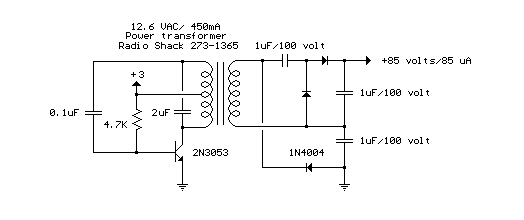
12V DC to 85V DC Converter
The circuit below is a DC to DC converter using a standard 12 VAC center tapped power transformer wired as a blocking oscillator. The circuit is not very efficient but will produce a high voltage usable for low power applications....

Simple Circuit 12V to 120V DC DC Converter
This is a simple circuit designed to convert 12V DC to 120V DC. The circuit comprises two main phases: the inverter stage and the rectifier and filter stage. The NE555 integrated circuit (IC1) is configured as an astable multivibrator, operating...

Isolated-dc-dc-converter
In this circuit, a TU31 shunt regulator is utilized to monitor the output voltage. The TU31 activates the LED of a 4N28 optocoupler, which delivers feedback to the MAX641 while ensuring isolation between the input voltage of +12 V and...

DC to DC converter electronic schematic
Individuals who frequently utilize battery-operated devices or require a negative voltage from a single positive source will find the following converter beneficial. This circuit can convert a 9 V positive battery voltage to a negative voltage using the well-known integrated...

case stepper
Beige Bag Software has been offering affordable and innovative circuit design tools since 1990. B2 Spice provides schematics as well as analog, digital, and mixed-mode electronic circuit simulation. It integrates with EAGLE and CADSTAR PCB software.
B2 Spice is a powerful...

3.3V and 5V DC DC converter circuit design using LT3692 DC converter dual tracking regulator
The LT3692 dual current mode PWM step-down DC-DC converter circuit, featuring two internal 3.5A switches, can be designed into a simple power supply circuit suitable for various electronic applications, such as distributed supply regulation or automotive circuits. The LT3692 provides...