


Dual Relay Driver Board Circuit Schematic
#relay driver
#BC547
#transistor
#common-emitter amplifier
#12 volt
#reed-relay
#input impedance
#switching circuit
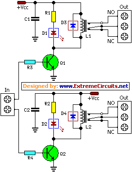
Description: This relay driver enhances the input impedance using a standard BC547 NPN transistor (or its equivalent). It is a widely used driver capable of operating various relays, including reed relays. Transistors Q1 and Q2 function as a simple common-emitter amplifier, significantly increasing the effective sensitivity of the 12-volt relay coil by approximately 100 times. In other terms, the current gain for this circuit is 100. This configuration effectively reduces the relay's sensitivity to a few volts. Resistors R3 and R4 limit the input current to Q1 and Q2, ensuring safe operation. Diodes D3 and D4 serve as EMF dampers, filtering out any sparking that occurs when the relay is activated.
The relay driver circuit utilizes a BC547 NPN transistor, which acts as a key component in controlling the relay's operation. The common-emitter configuration of transistors Q1 and Q2 allows for significant amplification of the input signal, which is crucial for driving the relay coil effectively. The 100-fold increase in current gain means that a small input current can activate the relay, making the circuit highly efficient.
Resistors R3 and R4 play an essential role in protecting the transistors from excessive current, which could lead to damage or malfunction. By limiting the input current, these resistors ensure that the transistors operate within their safe limits, enhancing the reliability of the circuit.
Diodes D3 and D4 are critical for managing inductive kickback generated when the relay coil is de-energized. This kickback can produce high-voltage spikes that may damage the transistors or other components in the circuit. The diodes effectively clamp these voltage spikes, allowing for smoother operation and preventing potential damage.
Overall, this relay driver circuit design is a robust solution for controlling various types of relays, providing both efficiency and protection for the components involved. The careful selection of components and their configuration ensures a reliable performance in various applications where relay control is required.This relay driver boosts the input impedance with a regular BC547 NPN transistor (or equivalent). Very common driver. It can drive a variety of relays, including a reed-relay. Transistor Q1and Q2 are a simple common-emitter amplifier that increases the effective sensitivity of the 12 volt relay coil about a 100 times, or in other words, the current gain for this circuit is 100. Using this setup reduces the relay sensitivity to a few volts. R3 and R4 restricts the input current to Q1 and Q2 to a safe limit. Diodes D3 and D4 are EMF dampers and filter off any sparking when the relay
The relay driver circuit utilizes a BC547 NPN transistor, which acts as a key component in controlling the relay's operation. The common-emitter configuration of transistors Q1 and Q2 allows for significant amplification of the input signal, which is crucial for driving the relay coil effectively. The 100-fold increase in current gain means that a small input current can activate the relay, making the circuit highly efficient.
Resistors R3 and R4 play an essential role in protecting the transistors from excessive current, which could lead to damage or malfunction. By limiting the input current, these resistors ensure that the transistors operate within their safe limits, enhancing the reliability of the circuit.
Diodes D3 and D4 are critical for managing inductive kickback generated when the relay coil is de-energized. This kickback can produce high-voltage spikes that may damage the transistors or other components in the circuit. The diodes effectively clamp these voltage spikes, allowing for smoother operation and preventing potential damage.
Overall, this relay driver circuit design is a robust solution for controlling various types of relays, providing both efficiency and protection for the components involved. The careful selection of components and their configuration ensures a reliable performance in various applications where relay control is required.This relay driver boosts the input impedance with a regular BC547 NPN transistor (or equivalent). Very common driver. It can drive a variety of relays, including a reed-relay. Transistor Q1and Q2 are a simple common-emitter amplifier that increases the effective sensitivity of the 12 volt relay coil about a 100 times, or in other words, the current gain for this circuit is 100. Using this setup reduces the relay sensitivity to a few volts. R3 and R4 restricts the input current to Q1 and Q2 to a safe limit. Diodes D3 and D4 are EMF dampers and filter off any sparking when the relay

TYPICAL TRANSISTOR CIRCUIT
This is a silicon transistor circuit showing typical voltage values. When the forward base/emitter voltage is 0.6 to 0.7 V, the transistor is silicon. Germanium transistors will have a forward base/emitter bias voltage of 0.2 to 0.3 V. This is...

Transistor Mosfet pairs to drive LED cube layers
None of those devices is very suitable. The drivers aren't specified to operate with 3.3V gate signals, and although the typical graph shows that a...
The devices referenced in the original input are not appropriate for the intended application due to...

ND838 application circuit
Figures (A), (B), (C), and (D) illustrate outputs that can directly drive transistors, thyristors, relays, CMOS circuits, and TTL circuits.
The described figures depict various output configurations capable of interfacing with different electronic components. Each output is designed to provide the...

Blinker circuit 2
The circuit depicted in Figure 13-4 utilizes triode control. Two transistors, VTi and VTz, are coupled via a capacitor (C) to alternately turn on and off, producing a flashing light effect. The flash frequency is influenced by the capacitance of...

2 channel audio mixer circuit using transistors
This two-channel audio mixer utilizes 2N3904 transistors to create two preamplifiers. The first preamplifier is designed for high gain, suitable for microphone input, while the second preamplifier allows for control over the audio level input. The audio mixer requires a...

One Transistor Audio Mixer
The simplest one-transistor audio mixer circuit diagram available. It utilizes a single transistor and can accommodate multiple audio signals, limited only by the user's budget. BC10.
The one-transistor audio mixer circuit is a fundamental design that demonstrates the principles of audio...

Relay Driver with Strobe
The LM111 comparator can be utilized to design a relay driver with a TTL strobe, which enhances control over the relay driver. The strobe signal can be used to manage the relay operation more effectively.
The LM111 is a high-speed voltage...

Direct Coupled Discrete Astable Multivibrator circuit
This flip-flop circuit functions as a free-running astable multivibrator, where the bases and collectors of both emitter-biased transistors are directly coupled. The switching action is facilitated by a capacitor in each emitter circuit, resulting in the generation of triangle waves...

The Transistor Amplifier-P2
The three circuits described provide a constant current to the LED (or LEDs) when the supply voltage reaches 15V or higher. The second and third circuits can be activated or deactivated through the input line by turning on the top...