


HC132 Selling Leads
#solid-state relay
#overload protection
#current limiting
#short circuit detection
#fault-condition signal
#transistor
#flip-flop
#automotive circuits

Description: The circuit safeguards a solid-state relay from overload conditions. It limits current, automatically disconnects the load upon detecting a short circuit, and generates a fault-condition output signal. During normal operation, the controlling pulse train generator (ptP) sets the flip-flop, IC1, which activates transistor Q1. When Q1 is turned on, current flows through the input of the solid-state relay, thereby activating the relay. In the event of an overcurrent or fault condition, the excessive load current flowing through the relay generates sufficient voltage across the sense resistor R5 to activate one of the optoisolators, IC4A or IC4B. The output transistor of the optoisolator redirects current away from the input of the solid-state relay, limiting the current that the relay's output can deliver. If the overload is significant enough, the optoisolator raises the input of the Schmitt trigger above its threshold, which resets the flip-flop and deactivates the solid-state relay. Resistor R2 serves two purposes: it ensures that the input to the Schmitt trigger remains below 5 V to prevent latch-up and acts as part of an RC filter in conjunction with capacitor C1. This RC filter mitigates the risk of spurious triggering of the Schmitt trigger. The output from the flip-flop can be utilized to signal overload conditions to the controlling pulse train generator.
The described circuit functions as a protective mechanism for solid-state relays, primarily focusing on preventing damage due to overloads and short circuits. The operational sequence begins with the controlling pulse train generator (ptP), which initiates the flip-flop (IC1). The flip-flop's output controls transistor Q1, allowing current to flow through the relay's input, thus activating the relay to perform its intended function.
In the event of an overcurrent situation, the circuit is designed to detect excessive current through the sense resistor R5. When the current exceeds a predetermined threshold, it generates a voltage that activates one of the optoisolators (IC4A or IC4B). The optoisolator's output transistor effectively shunts the current away from the relay's input, limiting the amount of current that can pass through the relay's output. This action prevents potential damage to the relay and the connected load.
If the overload condition persists and the voltage across the sense resistor continues to rise, the optoisolator will trigger the Schmitt trigger, which is designed to provide a clean switching response. The Schmitt trigger's input is monitored closely, and once the voltage exceeds its threshold, it resets the flip-flop, which in turn deactivates the solid-state relay. This ensures that the load is disconnected during fault conditions, thereby protecting both the relay and the load.
Resistor R2 plays a critical role in maintaining the integrity of the circuit. It limits the voltage at the Schmitt trigger input to below 5 V, preventing latch-up conditions that could lead to erratic behavior. Additionally, in conjunction with capacitor C1, R2 forms an RC filter that smooths out any potential noise or voltage spikes, protecting the Schmitt trigger from false triggering events.
The output from the flip-flop can be utilized to communicate overload conditions back to the controlling pulse train generator, allowing for further action or monitoring. This circuit design integrates robust features that ensure reliable operation and protection of solid-state relays in various applications.The circuit protects a solid-state relay from overloads. The circuit limits current, automatically discon-nects the load after detecting a short circuit, and develops a fault-condition output signal. In normal operation, the controlling ptP sets the flip-flop, IC1, which turns on transistor Q1. When Q1 turns on, current flows through the solid-sta te relay`s input, thus activating the relay. If an overcurrent or fault condition occurs, the excessive load current flowing through the relay develops enough potential across sense resistor R5 to turn on one of the optoisolators, IC4A or IC4B. The optoisolator`s output transistor diverts current around the solid-state relay`s input, which limits the cur-rent that the relay`s output can pass.
If the overload is severe enough, the optoisolator pulls the input of the Schmitt trigger above its threshold, thus clearing the flip-flop and turning off the solid-state relay. R2 has two functions: It keeps the input of the Schmitt trigger below 5 V max. to prevent latchup, and it forms an RC filter in conjunction with C1. The RC filter prevents spurious triggering of the Schmitt trigger. You can use the output of the flip-flop to signal overload conditions to the controlling P.
The described circuit functions as a protective mechanism for solid-state relays, primarily focusing on preventing damage due to overloads and short circuits. The operational sequence begins with the controlling pulse train generator (ptP), which initiates the flip-flop (IC1). The flip-flop's output controls transistor Q1, allowing current to flow through the relay's input, thus activating the relay to perform its intended function.
In the event of an overcurrent situation, the circuit is designed to detect excessive current through the sense resistor R5. When the current exceeds a predetermined threshold, it generates a voltage that activates one of the optoisolators (IC4A or IC4B). The optoisolator's output transistor effectively shunts the current away from the relay's input, limiting the amount of current that can pass through the relay's output. This action prevents potential damage to the relay and the connected load.
If the overload condition persists and the voltage across the sense resistor continues to rise, the optoisolator will trigger the Schmitt trigger, which is designed to provide a clean switching response. The Schmitt trigger's input is monitored closely, and once the voltage exceeds its threshold, it resets the flip-flop, which in turn deactivates the solid-state relay. This ensures that the load is disconnected during fault conditions, thereby protecting both the relay and the load.
Resistor R2 plays a critical role in maintaining the integrity of the circuit. It limits the voltage at the Schmitt trigger input to below 5 V, preventing latch-up conditions that could lead to erratic behavior. Additionally, in conjunction with capacitor C1, R2 forms an RC filter that smooths out any potential noise or voltage spikes, protecting the Schmitt trigger from false triggering events.
The output from the flip-flop can be utilized to communicate overload conditions back to the controlling pulse train generator, allowing for further action or monitoring. This circuit design integrates robust features that ensure reliable operation and protection of solid-state relays in various applications.The circuit protects a solid-state relay from overloads. The circuit limits current, automatically discon-nects the load after detecting a short circuit, and develops a fault-condition output signal. In normal operation, the controlling ptP sets the flip-flop, IC1, which turns on transistor Q1. When Q1 turns on, current flows through the solid-sta te relay`s input, thus activating the relay. If an overcurrent or fault condition occurs, the excessive load current flowing through the relay develops enough potential across sense resistor R5 to turn on one of the optoisolators, IC4A or IC4B. The optoisolator`s output transistor diverts current around the solid-state relay`s input, which limits the cur-rent that the relay`s output can pass.
If the overload is severe enough, the optoisolator pulls the input of the Schmitt trigger above its threshold, thus clearing the flip-flop and turning off the solid-state relay. R2 has two functions: It keeps the input of the Schmitt trigger below 5 V max. to prevent latchup, and it forms an RC filter in conjunction with C1. The RC filter prevents spurious triggering of the Schmitt trigger. You can use the output of the flip-flop to signal overload conditions to the controlling P.

Motor time division control circuit composed of transistor and NE555
Figure 2-32 (a) illustrates the time control diagram for a motor operated by switch S1. When S1 is set to position 1, the power driver circuit supplies current to the motor, enabling it to run. When S1 is switched to...

Direct Coupled Discrete Astable Multivibrator circuit
This flip-flop circuit functions as a free-running astable multivibrator, where the bases and collectors of both emitter-biased transistors are directly coupled. The switching action is facilitated by a capacitor in each emitter circuit, resulting in the generation of triangle waves...

Spare-flip-flop-inverter
The circuit utilizes one-half of a dual D flip-flop as an inverter. When the input signal decreases, the flip-flop resets, causing its Q output to increase. Conversely, when the input signal increases, the reset line is released, and the Q...

Alternating current voltage amplifier transistor
An alternating current voltage amplifier transistor AC path is described. In AC analysis, the internal resistance of the AC supply voltage source is low, which corresponds to a short circuit signal. Consequently, the alternating voltage terminal Vcc is considered to...
Cable TV amplifier Using 2 Transistor
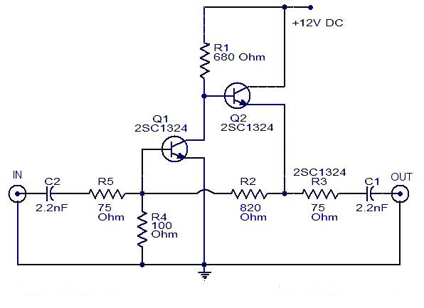
This is a cable TV amplifier utilizing two transistors. The amplifier circuit is designed for cable TV systems using 75 Ohm coaxial cables and operates effectively up to 150 MHz. Transistor T1 is responsible for amplification, providing an expected gain...

basic transistor circuits for beginners explored
This article compiles small transistor circuits and configurations suitable for beginners, including current amplifiers, limiters, oscillators, and latches. A simple current amplifier circuit can be constructed using just a couple of NPN transistors. Additionally, two transistors and resistors can be...
Astable Multivibrator with 2 Transistors
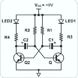
This circuit is straightforward and easy to construct, utilizing two transistors as active components along with several passive components such as resistors, capacitors, and two LEDs. The circuit employs the MPS2222 transistor, though any NPN type transistor can be used...

Nicad Battery Charger
This simple charger utilizes a single transistor as a constant current source. The voltage across a pair of 1N4148 diodes biases the base of the BD140 medium power transistor. The base-emitter voltage of the transistor and the forward voltage drop...

Digitally controlled threshold detector
This circuit utilizes small switching transistors, with a maximum motor drive current limited to approximately 250 mA at 5V. Testing has been conducted across a voltage range from 3V to 21V, and with certain component modifications, it may be applicable...