


High-performance-video-switch
#video switch
#amplifier
#NE5539
#termination resistor
#gain control
#input isolation
#high-performance
#load change

Description: This figure illustrates a one-of-two switch featuring a summing amplifier. The video source's line can be terminated either externally or internally to switch RO. With this termination resistor, a load change of less than 10 ohms will be perceived by the source when the switch changes state. Consequently, input isolation amplifiers are not necessary. R4 can be adjusted to control circuit gain but should never be less than 1400 ohms, as the NE5539 is internally compensated for gain values greater than seven. A value of approximately 2500 ohms for R4 will configure the circuit gain close to unity. Furthermore, the circuit output impedance is determined by R6, while R5 establishes the output DC offset to near zero.
The schematic represents a one-of-two switch configuration utilizing a summing amplifier to manage video signal routing. This configuration allows for flexible signal termination, either externally or internally, to the designated switching point (switch RO). The termination resistor plays a crucial role in minimizing the load change perceived by the video source during state transitions of the switch, ensuring that the source remains stable and unaffected by minor load variations, which is critical for maintaining signal integrity.
The NE5539 operational amplifier is employed in this design due to its high performance and internal compensation, which simplifies gain adjustments. The resistor R4 is pivotal in setting the gain of the amplifier circuit. It is essential to maintain R4 at a value no less than 1400 ohms to ensure proper operation within the specified gain range. A typical setting of 2500 ohms for R4 will yield a gain close to unity, allowing for effective signal amplification without introducing excessive noise or distortion.
The output impedance of the circuit is defined by resistor R6, which is essential for matching the output stage to subsequent circuit components. This matching is crucial for optimizing signal transfer and minimizing reflections in high-frequency applications. Resistor R5 is used to adjust the output DC offset, ensuring that the output signal remains centered around zero volts, which is particularly important for AC-coupled applications where DC offsets can introduce distortion or affect downstream processing.
Overall, this circuit design provides a robust solution for managing video signals with minimal interference and optimal performance, making it suitable for a variety of audio-visual applications.This figure shows a one-of-two switch with a sunnning amplifier. The video source"s line can be terminated either externally or internally to switch RO. With this termination resistor, a load change of less than 1 0 will be seen by the source when the switch changes state. For this reason, input isolation amplifiers are. not necessary. R4 can be varied to control circuit gain, but should never be less than 1400 0 since the NE5539 is internally compensated for gain values greater than seven.
A value of approximately 2500 {} for R4 will set circuit gain to near unity. Additionally, the circuit output impedance is set by R6, and R5 sets the output de offset to near zero.
The schematic represents a one-of-two switch configuration utilizing a summing amplifier to manage video signal routing. This configuration allows for flexible signal termination, either externally or internally, to the designated switching point (switch RO). The termination resistor plays a crucial role in minimizing the load change perceived by the video source during state transitions of the switch, ensuring that the source remains stable and unaffected by minor load variations, which is critical for maintaining signal integrity.
The NE5539 operational amplifier is employed in this design due to its high performance and internal compensation, which simplifies gain adjustments. The resistor R4 is pivotal in setting the gain of the amplifier circuit. It is essential to maintain R4 at a value no less than 1400 ohms to ensure proper operation within the specified gain range. A typical setting of 2500 ohms for R4 will yield a gain close to unity, allowing for effective signal amplification without introducing excessive noise or distortion.
The output impedance of the circuit is defined by resistor R6, which is essential for matching the output stage to subsequent circuit components. This matching is crucial for optimizing signal transfer and minimizing reflections in high-frequency applications. Resistor R5 is used to adjust the output DC offset, ensuring that the output signal remains centered around zero volts, which is particularly important for AC-coupled applications where DC offsets can introduce distortion or affect downstream processing.
Overall, this circuit design provides a robust solution for managing video signals with minimal interference and optimal performance, making it suitable for a variety of audio-visual applications.This figure shows a one-of-two switch with a sunnning amplifier. The video source"s line can be terminated either externally or internally to switch RO. With this termination resistor, a load change of less than 1 0 will be seen by the source when the switch changes state. For this reason, input isolation amplifiers are. not necessary. R4 can be varied to control circuit gain, but should never be less than 1400 0 since the NE5539 is internally compensated for gain values greater than seven.
A value of approximately 2500 {} for R4 will set circuit gain to near unity. Additionally, the circuit output impedance is set by R6, and R5 sets the output de offset to near zero.

Amplifier Timer Circuit Schematic
This circuit turns off an amplifier or any other device when it remains idle for 15 minutes. It is powered by the amplifier's tape output.
The described circuit functions as an automatic power management system, designed to enhance energy efficiency by...
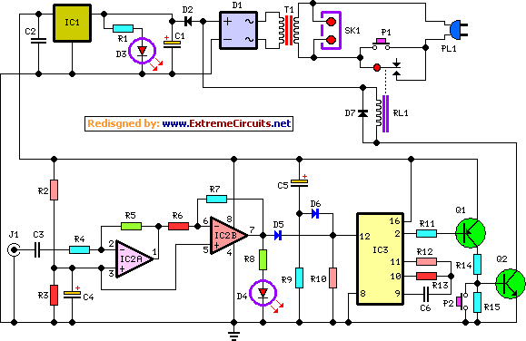
amplifier timer circuit schematic
This circuit deactivates an amplifier or any connected device when a low-level audio signal at its input is absent for at least 15 minutes. By pressing P1, the device is powered on, supplying power to any appliance connected to SK1....
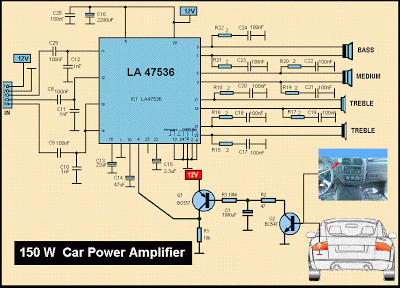
Schematic MP3 Car Audio Power AmplifierCircuits
This is a diagram of a car audio active loudspeaker utilizing the LF353 operational amplifier from National Semiconductor. For optimal performance, the NE5532 is recommended to split the audio signal into three frequency bands using an active filter. The SANYO...

Emitter negative feedback differential amplifier gain control circuit
A controllable gain amplifier functions as an automatic gain control circuit within the execution unit. The primary methods for controlling the amplifier's gain involve two approaches: one is by adjusting certain parameters of the amplifier itself, such as emitter current,...

Power Supply For Amplifiers
For the 60W amplifier, a nominal (full load) supply of +/- 35V is required, so a 25-0-25 secondary is ideal - however, see Updates, below. The circuit for the supply is shown below, and uses separate rectifiers, capacitors and fuses...

Video Switch for Intercom System
Nowadays, many intercom units are equipped with video cameras, allowing users to see as well as hear who is at the door. Unfortunately, the camera lens is...
Intercom systems with integrated video capabilities enhance security and convenience by enabling visual identification...

General-Purpose Output Amplifier Circuit
This general-purpose amplifier has a bandwidth of approximately 20 MHz and it uses an LM733/NE592 video amplifier integrated circuit. This circuit can be utilized as a line driver or as a LAN line driver.
The circuit employs the LM733/NE592 video amplifier...

Ears and Speakers Protector
Occasionally, the output volume of an amplifier can be excessively high, leading to discomfort and potential damage to both the listener's ears and the loudspeaker. The circuit...
Amplifiers are crucial components in audio systems, responsible for boosting audio signals to drive...

gated pulse descrambler
This circuit consists of an amplifier and a video detector with a second subcarrier detector for synchronization recovery purposes. A pulse-former circuit modulates the gain of the main channel, increasing it during synchronization intervals.
The circuit is designed to enhance video...