


Latch Switch
#latch switch
#push switch
#load control
#relay
#power control
#circuit switching
#battery powered
#electrical outlet
#non-locking switch

Description: In this circuit a non-locking push switch is used to activate a load. The load remains switched on until power is removed from the circuit. The load is represented by R5 and D1, but could be a lamp, a relay or another circuit. S2 breaks power to the circuit but could be omitted altogether. If S2 is left out, then reset would be by disconnecting the power; this would mean unplugging the battery if battery powered or disconnecting from the electrical outlet. More: When first plugged in (or S2 is operated) C1 charges via the base emitter junction of Q1 and hence a brief positive pulse is applied. Q1 will switch on and be saturated, its collector emitter voltage being close to zero volts. Q2 is therefore off, and the
This circuit utilizes a non-locking push switch (S1) to control the activation of a load, which can be represented by various components such as a resistor (R5) and a diode (D1), or potentially a lamp or relay. The circuit is designed such that the load remains activated until the power supply is interrupted. An optional switch (S2) can be included to break the power supply to the circuit, allowing for a reset mechanism. If S2 is excluded, the only method to reset the circuit would involve disconnecting the power source, such as unplugging a battery or disconnecting from an electrical outlet.
Upon initial power application, or when S2 is toggled, the capacitor (C1) begins to charge through the base-emitter junction of the transistor (Q1). This charging process generates a brief positive pulse at the base of Q1, which causes Q1 to enter saturation. In the saturated state, the collector-emitter voltage of Q1 approaches zero volts, effectively allowing current to flow through the load. With Q1 in this state, the second transistor (Q2) remains off, preventing any unwanted activation of additional components in the circuit.
The design of this circuit is particularly useful in applications where a momentary switch is desired to control a load that remains on until power is removed. The inclusion of C1 allows for a smooth transition during the activation phase, ensuring that the load is turned on reliably. The optional switch S2 provides flexibility for the user, enabling a straightforward method to reset the circuit without needing to physically disconnect the power supply. Overall, this circuit offers a simple yet effective solution for controlling various loads in electronic applications.In this circuit a non-locking push switch is used to activate a load. The load remains switched on until power is removed from the circuit. The load is represented by R5 and D1, but could be a lamp, a relay or another circuit. S2 breaks power to the circuit but could be omitted altogether. If S2 is left out, then reset would be by disconnecting the power; this would mean unplugging the battery if battery powered or disconnecting from the electrical outlet. When first plugged in (or S2 is operated) C1 charges via the base emitter junction of Q1 and hence a brief positive pulse is applied. Q1 will switch on and be saturated, its collector emitter voltage being close to zero volts. Q2 is therefore off, and the
This circuit utilizes a non-locking push switch (S1) to control the activation of a load, which can be represented by various components such as a resistor (R5) and a diode (D1), or potentially a lamp or relay. The circuit is designed such that the load remains activated until the power supply is interrupted. An optional switch (S2) can be included to break the power supply to the circuit, allowing for a reset mechanism. If S2 is excluded, the only method to reset the circuit would involve disconnecting the power source, such as unplugging a battery or disconnecting from an electrical outlet.
Upon initial power application, or when S2 is toggled, the capacitor (C1) begins to charge through the base-emitter junction of the transistor (Q1). This charging process generates a brief positive pulse at the base of Q1, which causes Q1 to enter saturation. In the saturated state, the collector-emitter voltage of Q1 approaches zero volts, effectively allowing current to flow through the load. With Q1 in this state, the second transistor (Q2) remains off, preventing any unwanted activation of additional components in the circuit.
The design of this circuit is particularly useful in applications where a momentary switch is desired to control a load that remains on until power is removed. The inclusion of C1 allows for a smooth transition during the activation phase, ensuring that the load is turned on reliably. The optional switch S2 provides flexibility for the user, enabling a straightforward method to reset the circuit without needing to physically disconnect the power supply. Overall, this circuit offers a simple yet effective solution for controlling various loads in electronic applications.In this circuit a non-locking push switch is used to activate a load. The load remains switched on until power is removed from the circuit. The load is represented by R5 and D1, but could be a lamp, a relay or another circuit. S2 breaks power to the circuit but could be omitted altogether. If S2 is left out, then reset would be by disconnecting the power; this would mean unplugging the battery if battery powered or disconnecting from the electrical outlet. When first plugged in (or S2 is operated) C1 charges via the base emitter junction of Q1 and hence a brief positive pulse is applied. Q1 will switch on and be saturated, its collector emitter voltage being close to zero volts. Q2 is therefore off, and the

Delaying the release of DC relay circuit
To fulfill the requirements of a control loop, it is often necessary to utilize an electromagnetic relay or a transistor relay to either accelerate or delay an action, thereby forming an acceleration or delay circuit. The circuit depicted in Figure...
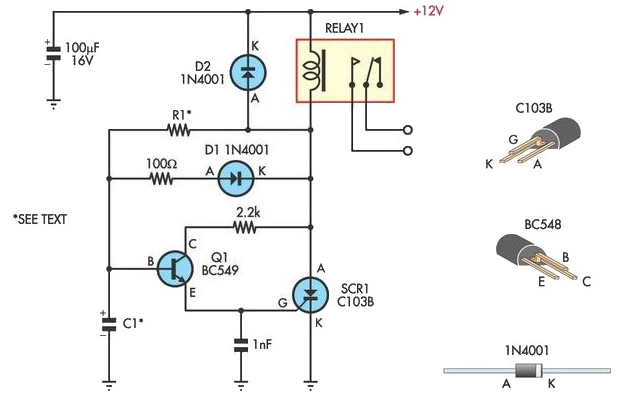
Handy Time Delay With Relay Output
This circuit is designed to provide delayed relay switching action at power on. The delay is a function of the time constant produced by the combination of components.
The circuit operates by utilizing a timing element, typically a resistor-capacitor (RC) network,...
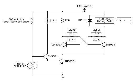
light activated relay
This circuit is similar to the previous one but incorporates a photoresistor to trigger the flip-flop instead of a push button. A bias resistor is placed in series with the photoresistor to ensure that adequate voltage is present at the...

Run/Stop Relay Circuit
Safety is a significant concern in many motor-driven applications. This is particularly true in industrial settings where motion begins immediately upon the application of power.
In motor-driven applications, safety mechanisms are essential to prevent accidents and ensure the well-being of operators...

2004 chevy impala: relay diagram passenger side fuse block
A 2004 Chevrolet Impala is experiencing issues with the rear defogger. The owner is unable to locate the fuse for the rear defogger, although the relay has been found. Both the manual and the vehicle's diagram indicate a 30-amp fuse,...

DC relay circuit to accelerate the release
A DC relay or contactor is utilized to enhance the excitation pull-in and release mechanisms in a circuit. The relay circuit, as depicted in Figure 6-28, facilitates improved return line efficiency. When the control relay KAi is activated, its normally...

Relay Fuse For Power Supplies Circuit
A method of adding overload protection to a power supply using a relay is shown. In each circuit, the relay must be reset by a momentary switch using a charge on capacitor C2. This prevents overload if the short still...

Input switching circuit
A relay is controlled by a closed circuit in a digital logic setup, utilizing a touch input switching circuit.
The described circuit involves a relay that operates based on a closed circuit condition within a digital logic framework. The relay serves...

Relay type starting circuit diagram
The figure below illustrates the use of a relay in the starting circuit. The power input connects through a resistor R, which serves two purposes: first, it prevents a large current from the capacitor C1 from affecting the power supply...