


Load detector Mains Switch
#load detector
#mains switch
#current sensing
#comparator
#relay
#smart outlets
#automated switching
#master-slave
#power management

Description: This circuit will automatically switch on several mains-powered "slave" loads when a "master" load is turned on. For example, it will switch on the amplifier and CD player in a stereo system when the receiver is turned on. It works by sensing the current draw of the "master" device through a low value high wattage resistor using a comparator. The output of that comparator then switches on the "slave" relay. The circuit can be built into a power bar, extension cord or power center to provide a convenient set of "smart" outlets that switch on when the master appliance is powered (turn on the computer monitor and the computer, printer and other peripherals come on as well). More: C1, C3 2 10uF 35V Electrolytic Capacitor R1 1 0.1 Ohm 10W Resistor R2 1 27K 1/2W Resistor R3, R4 1 1K 1/4W Resistor R5 1 470K 1/4W Resistor R6 1 4.7K 1/2W Resistor R7 1 10K 1/4W Resistor D1, D2, D4 3 1N4004 Rectifier Diode D3 1 1N4744 15V 1 Watt Zener Diode U1 1 LM358N Dual Op Amp IC Q1 1 2N3904 NPN Transistor K1 1 Relay, 12VDC Coil, 120VAC 10A Contacts S1 1 SPST Switch 120AVC, 10A MISC 1 Board, Wire, Socket For U1, Case, Mains Plug, Socket This circuit is designed for 120V operation. For 240V operation, resistors R2 and R6 will need to be changed. A maximum of 5A can be used as the master unless the wattage of R1 is increased. S1 provides a manual bypass switch. This circuit is not isolated from the mains supply. Because of this, you must exercise extreme caution when working around the circuit if it is plugged in.
The circuit described functions as a master-slave power management system. It utilizes a low-value, high-wattage resistor (R1) to sense the current draw of the master device. When the master device is powered on, the current flowing through R1 generates a voltage drop that is detected by the operational amplifier (U1, an LM358N). The op-amp is configured as a comparator, which compares the voltage across R1 against a reference voltage set by resistors R2 and R6.
If the voltage across R1 exceeds the reference voltage, the output of the op-amp goes high, activating the NPN transistor (Q1, a 2N3904). This transistor acts as a switch that energizes the relay (K1), which in turn closes its contacts to power the slave devices. The relay is rated for 12VDC coil voltage and can handle AC loads up to 10A, allowing for multiple devices to be powered simultaneously.
Capacitors C1 and C3 (10µF) are used for power supply decoupling, ensuring stable operation of the op-amp by filtering out noise. Capacitor C2 (1µF) may serve a similar purpose or be involved in timing or stability for the comparator circuit. The diodes (D1, D2, D4 - 1N4004) provide rectification and protection against reverse voltage, while D3 (1N4744) serves as a Zener diode to maintain a stable reference voltage for the op-amp.
Resistors R3, R4, R5, R7 are involved in setting the gain and stability of the op-amp circuit. The SPST switch (S1) allows for manual bypassing of the automatic switching feature, providing a way to control the slave devices without needing to power the master device.
This circuit is designed for 120V mains operation, with provisions for modification for 240V by changing R2 and R6. Safety precautions are emphasized, as the circuit is not isolated from the mains, necessitating careful handling to avoid electrical hazards.This circuit will automatically switch on several mains-powered "slave" loads when a "master" load is turned on. For example, it will switch on the amplifier and CD player in a stereo system when the receiver is turned on.
It works by sensing the current draw of the "master" device through a low value high wattage resistor using a comparator. The output of that comparator then switches on the "slave" relay. The circuit can be built into a power bar, extension cord or power center to provide a convenient set of "smart" outlets that switch on when the master appliance is powered (turn on the computer monitor and the computer, printer and other peripherals come on as well).
C1, C3 2 10uF 35V Electrolytic Capacitor C2 1 1uF 35V Electrolytic Capacitor R1 1 0.1 Ohm 10W Resistor R2 1 27K 1/2W Resistor R3, R4 1 1K 1/4W Resistor R5 1 470K 1/4W Resistor R6 1 4.7K 1/2W Resistor R7 1 10K 1/4W Resistor D1, D2, D4 3 1N4004 Rectifier Diode D3 1 1N4744 15V 1 Watt Zener Diode U1 1 LM358N Dual Op Amp IC Q1 1 2N3904 NPN Transistor K1 1 Relay, 12VDC Coil, 120VAC 10A Contacts S1 1 SPST Switch 120AVC, 10A MISC 1 Board, Wire, Socket For U1, Case, Mains Plug, Socket This circuit is designed for 120V operation. For 240V operation, resistors R2 and R6 will need to be changed. A maximum of 5A can be used as the master unless the wattage of R1 is increased S1 provides a manual bypass switch.
THis circuit is not isolated from the mains supply. Because of this, you must exercise extreme caution when working around the circuit if it is plugged in.
The circuit described functions as a master-slave power management system. It utilizes a low-value, high-wattage resistor (R1) to sense the current draw of the master device. When the master device is powered on, the current flowing through R1 generates a voltage drop that is detected by the operational amplifier (U1, an LM358N). The op-amp is configured as a comparator, which compares the voltage across R1 against a reference voltage set by resistors R2 and R6.
If the voltage across R1 exceeds the reference voltage, the output of the op-amp goes high, activating the NPN transistor (Q1, a 2N3904). This transistor acts as a switch that energizes the relay (K1), which in turn closes its contacts to power the slave devices. The relay is rated for 12VDC coil voltage and can handle AC loads up to 10A, allowing for multiple devices to be powered simultaneously.
Capacitors C1 and C3 (10µF) are used for power supply decoupling, ensuring stable operation of the op-amp by filtering out noise. Capacitor C2 (1µF) may serve a similar purpose or be involved in timing or stability for the comparator circuit. The diodes (D1, D2, D4 - 1N4004) provide rectification and protection against reverse voltage, while D3 (1N4744) serves as a Zener diode to maintain a stable reference voltage for the op-amp.
Resistors R3, R4, R5, R7 are involved in setting the gain and stability of the op-amp circuit. The SPST switch (S1) allows for manual bypassing of the automatic switching feature, providing a way to control the slave devices without needing to power the master device.
This circuit is designed for 120V mains operation, with provisions for modification for 240V by changing R2 and R6. Safety precautions are emphasized, as the circuit is not isolated from the mains, necessitating careful handling to avoid electrical hazards.This circuit will automatically switch on several mains-powered "slave" loads when a "master" load is turned on. For example, it will switch on the amplifier and CD player in a stereo system when the receiver is turned on.
It works by sensing the current draw of the "master" device through a low value high wattage resistor using a comparator. The output of that comparator then switches on the "slave" relay. The circuit can be built into a power bar, extension cord or power center to provide a convenient set of "smart" outlets that switch on when the master appliance is powered (turn on the computer monitor and the computer, printer and other peripherals come on as well).
C1, C3 2 10uF 35V Electrolytic Capacitor C2 1 1uF 35V Electrolytic Capacitor R1 1 0.1 Ohm 10W Resistor R2 1 27K 1/2W Resistor R3, R4 1 1K 1/4W Resistor R5 1 470K 1/4W Resistor R6 1 4.7K 1/2W Resistor R7 1 10K 1/4W Resistor D1, D2, D4 3 1N4004 Rectifier Diode D3 1 1N4744 15V 1 Watt Zener Diode U1 1 LM358N Dual Op Amp IC Q1 1 2N3904 NPN Transistor K1 1 Relay, 12VDC Coil, 120VAC 10A Contacts S1 1 SPST Switch 120AVC, 10A MISC 1 Board, Wire, Socket For U1, Case, Mains Plug, Socket This circuit is designed for 120V operation. For 240V operation, resistors R2 and R6 will need to be changed. A maximum of 5A can be used as the master unless the wattage of R1 is increased S1 provides a manual bypass switch.
THis circuit is not isolated from the mains supply. Because of this, you must exercise extreme caution when working around the circuit if it is plugged in.

IC Magnitude Comparators
This Magnitude Comparator can be used to perform comparisons of two 8-bit binary or BCD words. The output provides both a P equals Q function and a P greater than Q function. A Magnitude Comparator is typically classified as standard...
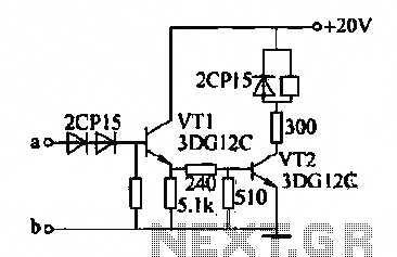
Relay control circuit
The motor winding is configured with delta transposition capacitance, designated as cl-C-3G. It operates as a DC LAN speed generator and is associated with a three-phase asynchronous motor, which is coaxially connected through a field winding powered by a 10V...
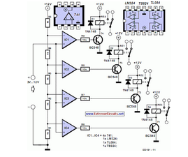
Reducing Relay Power Consumption
This circuit demonstrates that microprocessors, personal computers, and the latest ultra-accurate digital-to-analog converters (DACs) are excessive for the task of sequentially controlling four relays.
The circuit utilizes a simple microcontroller or a basic timer IC to manage the operation of four...

Sensitive Overload Sensor
The most effective method for measuring current in a circuit is to insert a sense resistor into the current path. A higher resistance results in a more accurate measurement; however, it can also impact the circuit's operation. Utilizing an active...

Relay Fuse For Power Supplies Circuit
A method of adding overload protection to a power supply using a relay is shown. In each circuit, the relay must be reset by a momentary switch using a charge on capacitor C2. This prevents overload if the short still...

output relay delay audio amplifier
This is a simple circuit designed for an audio amplifier project to control the speaker output relay. The purpose of this circuit is to manage the delay that activates the relay, which connects the speakers to the audio amplifier. The...

Dark and Light Activated Relay
The potentiometer adjusts the trigger level. The diode in the circuit diagram is specified as 1N914, which is suitable for light-duty relays; however, since the 1N914 is a signal diode, it is not ideal. A 1N4001 or a better alternative...

Time to start reversing relay control circuit
The circuit depicted in Figure 3-162 includes several components: SBi serves as the forward start button, SBz functions as the reverse start button, and SB3 is designated as the stop button. The resistance levels for the start switches are managed...

Power-Off Time Delay Relay
The two circuits demonstrate the operation of opening a relay contact shortly after the ignition or light switch is turned off. The capacitor becomes charged, and the relay remains closed until the voltage at the diode anode reaches 12 volts.
The...