


Load test control circuit diagram
#load test
#control circuit
#10A load
#power amplifier
#LED
#solenoids
#relays
#drive test
#external load

Description: The FIG load test is a control circuit designed for external loads up to 10A, commonly utilized in drive test power applications, power amplifiers, LED solenoids, and relays. It is capable of handling various resistive loads and features a voltage adjustment range of 1.2 to 50V, allowing for the maintenance of a constant load during testing. The circuit employs a power MOSFET (VT1) and a sense resistor (RA and RD) to manage power consumption, while a battery is used for isolation to address grounding issues. A 10-turn potentiometer (RP2) enhances accuracy and resolution. The wiper of RP2 provides a reference voltage to operational amplifier A1 through feedback, ensuring that the desired wiper voltage is present on resistor R5, thus controlling the load current through VT1. The bias current for A1, which can reach up to 3nA, flows through a series resistor (RD) and a resistor (RA), generating an error voltage that is amplified by four resistors (100). This error voltage is compared to the non-inverting input of A1, while the voltage from RP2 remains small and negligible. Capacitor C1 is included to enhance stability, and the series resistors RA and RD can adjust the output current across four ranges. During calibration, the battery and circuit are accessed, followed by a connection to a 5V/10A power source as the experimental load RL. The full-scale output is adjusted using RP2, and the exact 10A current is read with an ammeter. To verify the linearity of the circuit, RP2 is finely adjusted, and a 5A current is also measured with an ammeter. Resistors RB and RD are calibrated to ensure the accuracy of the remaining current range.
The FIG load test circuit is structured to provide precise control over load testing conditions. The integration of a power MOSFET (VT1) allows for efficient switching and management of high currents, while the sense resistors (RA and RD) are critical for monitoring the load current and ensuring accurate feedback to the control system. The use of a potentiometer (RP2) with a 10-turn configuration enables fine adjustments to the reference voltage, which is crucial for maintaining a stable output current during testing.
The operational amplifier (A1) plays a vital role in processing the feedback from the sense resistors, amplifying the error voltage to ensure that the load current remains within specified limits. The design includes provisions for stability enhancement through the use of capacitor C1, which mitigates any potential oscillations that may arise during operation.
Calibration procedures are essential for ensuring that the circuit operates within its intended specifications. By connecting the circuit to a known power source and adjusting the potentiometers, the user can establish a baseline for the output current. The ability to measure both 10A and 5A loads provides a comprehensive assessment of the circuit’s performance across its operational range.
In summary, the FIG load test circuit is a sophisticated electronic design that facilitates the testing of various electrical components under controlled conditions. Its focus on precision, stability, and adaptability makes it an invaluable tool in the field of electronics testing and validation.FIG load test is a control circuit. This external load circuit up to 10A, widely used in the drive test power, the power amplifier, LED solenoids and relays, and the carrying c apacity of the experiment. General resistive load different, it by a 1.2 50V voltage range adjustment load current to maintain a constant load test. Circuit power MOS-FET (VTl) and the sense resistor (RA a RD) load power consumption, battery used to isolate and solve the problem of grounding.
RP2 10-turn potentiometer, improve the accuracy and resolution. Wiper RP2 for Al provides a reference voltage through feedback to ensure prosperous wiper voltage present on R5, forcing the required load current through the VT1. Al bias current (up to 3nA) via an RD series resistor RA circulation, the current times and four resistors (100 obtained 30OnV error voltage.
This compared with the error voltage to provide the noninverting input of A1 by the voltage RP2 is small, negligible .Cl for enhancing stability, RA RD series resistor can be a 4 range of output current. During calibration, access the battery and the circuit, and then access 5V/l0A power as experimental load RL.
In RP2 for the next full-scale, adjusting RPl and read the exact 10 OOA current with ammeter. In order to check the linearity of the circuit, to accurately adjust the RP2, and reads 5, OOA current with ammeter. RB RD adjust a resistance calibration to the rest of the current range.
The FIG load test circuit is structured to provide precise control over load testing conditions. The integration of a power MOSFET (VT1) allows for efficient switching and management of high currents, while the sense resistors (RA and RD) are critical for monitoring the load current and ensuring accurate feedback to the control system. The use of a potentiometer (RP2) with a 10-turn configuration enables fine adjustments to the reference voltage, which is crucial for maintaining a stable output current during testing.
The operational amplifier (A1) plays a vital role in processing the feedback from the sense resistors, amplifying the error voltage to ensure that the load current remains within specified limits. The design includes provisions for stability enhancement through the use of capacitor C1, which mitigates any potential oscillations that may arise during operation.
Calibration procedures are essential for ensuring that the circuit operates within its intended specifications. By connecting the circuit to a known power source and adjusting the potentiometers, the user can establish a baseline for the output current. The ability to measure both 10A and 5A loads provides a comprehensive assessment of the circuit’s performance across its operational range.
In summary, the FIG load test circuit is a sophisticated electronic design that facilitates the testing of various electrical components under controlled conditions. Its focus on precision, stability, and adaptability makes it an invaluable tool in the field of electronics testing and validation.FIG load test is a control circuit. This external load circuit up to 10A, widely used in the drive test power, the power amplifier, LED solenoids and relays, and the carrying c apacity of the experiment. General resistive load different, it by a 1.2 50V voltage range adjustment load current to maintain a constant load test. Circuit power MOS-FET (VTl) and the sense resistor (RA a RD) load power consumption, battery used to isolate and solve the problem of grounding.
RP2 10-turn potentiometer, improve the accuracy and resolution. Wiper RP2 for Al provides a reference voltage through feedback to ensure prosperous wiper voltage present on R5, forcing the required load current through the VT1. Al bias current (up to 3nA) via an RD series resistor RA circulation, the current times and four resistors (100 obtained 30OnV error voltage.
This compared with the error voltage to provide the noninverting input of A1 by the voltage RP2 is small, negligible .Cl for enhancing stability, RA RD series resistor can be a 4 range of output current. During calibration, access the battery and the circuit, and then access 5V/l0A power as experimental load RL.
In RP2 for the next full-scale, adjusting RPl and read the exact 10 OOA current with ammeter. In order to check the linearity of the circuit, to accurately adjust the RP2, and reads 5, OOA current with ammeter. RB RD adjust a resistance calibration to the rest of the current range.

LED Flasher IV
This circuit will flash a string of LEDs, typically 16, with direct connection to the mains and with a period adjustable between 1 and 4 seconds depending on the setting of the 22K/1W pot. Operation at 110V should also be...

gym agility simple strategy
This circuit is a two-player game that combines strategy, speed, and physical agility. Each player has a row of four LEDs in front of them, with a push-button next to each LED. Pressing a button illuminates the corresponding LED. The...
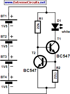
LED Light Pen
Physicians and repair engineers frequently utilize small light pens for visual examination purposes. Although these pens are rugged and can be expensive, their vulnerability lies in the bulb, which is a replaceable component. In practice, this often translates to the...

Simple power Supply for LEDS
LEDs are great display tools. Their prices have decreased to a point where they are replacing more conventional light sources. In one sense, their characteristic need for low voltages is an advantage, e.g., compatibility with I.C. drives, but this voltage...

Mains Operated LED Circuit
This is a straightforward and effective LED circuit that can be powered directly from an AC mains supply ranging from 100 volts to 230 volts. The circuit can serve as a mains power indicator or a night lamp. Resistors R1...

Key Illuminator Circuit
Used as a 10-second momentary illuminator, this circuit can be useful in other applications as well. Pressing SI charges CI, which holds Q1 on and keeps the LED lit for about 10 seconds.
The circuit described functions as a momentary illuminator,...

Police Car Lights with LEDs
This circuit simulates the flashing lights of a police car, similar to those seen on British police vehicles. The operational amplifier IC1a functions as a square wave oscillator, with an adjustable frequency controlled by the variable resistor VR1 to achieve...
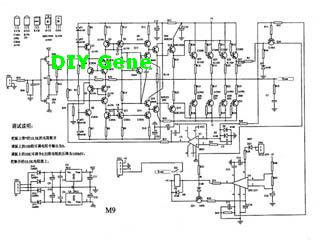
Complete Solid state M-9 Power Amplifier
The following circuit illustrates a complete solid-state M-9 power amplifier circuit diagram. Features include a DC servo that acts as a loudspeaker protection circuit.
The solid-state M-9 power amplifier circuit is designed to deliver high-quality audio amplification while ensuring the safety...

ve170 monitor repair with led
The issue with this monitor is that the power supply for the vacuum tube backlighting fails. The initial step involves completely disassembling the monitor into smaller components, followed by the careful removal of the gold-colored trays that hold the vacuum...