


Normally-closed-half-wave
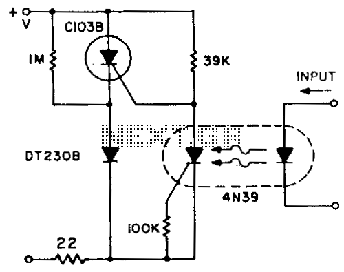
Description: A normally closed contact circuit that provides zero-voltage switching is designed around the 4N39 SCR optocoupler. The circuit illustrates the method of modifying the normally open contact circuit by using the photo SCR to hold off the trigger SCR.
The circuit utilizes the 4N39 optocoupler, which is a device that combines an LED and a phototransistor in a single package, allowing for electrical isolation between its input and output. In this application, the optocoupler serves as a means to control the triggering of a silicon-controlled rectifier (SCR) while ensuring that the circuit remains in a normally closed state until a specific condition is met.
In a typical configuration, the input side of the 4N39 is connected to a control signal that activates the LED. When the LED is energized, it emits light that activates the phototransistor within the optocoupler. This action allows current to flow through the output side, which is connected to the gate of the SCR. The SCR remains off until the phototransistor conducts, providing a zero-voltage switching condition. This means that the SCR can be triggered to conduct without the risk of voltage spikes, which is beneficial for protecting sensitive components in the circuit.
The modification of the normally open contact circuit involves using the photo SCR to hold off the trigger SCR until the appropriate conditions are met. When the control signal is removed, the LED in the optocoupler turns off, causing the phototransistor to cease conduction. This action effectively turns off the SCR, returning the circuit to its normally closed state.
This configuration is particularly useful in applications requiring isolation between control and power circuits, such as in industrial automation, where it is essential to prevent high voltages from affecting low-voltage control signals. Additionally, the zero-voltage switching feature minimizes electromagnetic interference (EMI) and prolongs the life of the components by reducing wear associated with high-voltage switching.
Overall, this normally closed contact circuit design using the 4N39 SCR optocoupler exemplifies an effective approach to achieving reliable control in electronic systems while maintaining safety and efficiency.A normally closed contact circuit that provides zero-voltage switching is designed around the 4N39 SCR optocoupler. The circuit illustrates the method of modifying the normally open contact circuit by using the photo SCR to hold off the trigger SCR.
The circuit utilizes the 4N39 optocoupler, which is a device that combines an LED and a phototransistor in a single package, allowing for electrical isolation between its input and output. In this application, the optocoupler serves as a means to control the triggering of a silicon-controlled rectifier (SCR) while ensuring that the circuit remains in a normally closed state until a specific condition is met.
In a typical configuration, the input side of the 4N39 is connected to a control signal that activates the LED. When the LED is energized, it emits light that activates the phototransistor within the optocoupler. This action allows current to flow through the output side, which is connected to the gate of the SCR. The SCR remains off until the phototransistor conducts, providing a zero-voltage switching condition. This means that the SCR can be triggered to conduct without the risk of voltage spikes, which is beneficial for protecting sensitive components in the circuit.
The modification of the normally open contact circuit involves using the photo SCR to hold off the trigger SCR until the appropriate conditions are met. When the control signal is removed, the LED in the optocoupler turns off, causing the phototransistor to cease conduction. This action effectively turns off the SCR, returning the circuit to its normally closed state.
This configuration is particularly useful in applications requiring isolation between control and power circuits, such as in industrial automation, where it is essential to prevent high voltages from affecting low-voltage control signals. Additionally, the zero-voltage switching feature minimizes electromagnetic interference (EMI) and prolongs the life of the components by reducing wear associated with high-voltage switching.
Overall, this normally closed contact circuit design using the 4N39 SCR optocoupler exemplifies an effective approach to achieving reliable control in electronic systems while maintaining safety and efficiency.A normally closed contact circuit that provides zero-voltage switching is designed around the 4N39 SCR optocoupler. The circuit illustrates the method of modifying the normally open contact circuit by using the photo SCR to hold off the trigger SCR.

Who-is-first
This control circuit utilizes two silicon-controlled rectifiers (SCRs) to ensure that only one lamp is illuminated at any given time. The first lamp (I1) is activated by SCR1, which is triggered when switch S1 is pressed. Similarly, the second lamp...

Scr-tester
The cathode, anode, and gate of the Device Under Test (DUT) are connected to the unit's K, A, and G terminals, respectively. Pressing switch S1 supplies a gate current to the DUT, triggering it to turn on. Resistor R1 limits...

First-Response Monitor with SCR (Quiz Alarm)
A pair of cross-coupled SCRs can be utilized to create a first-response monitor circuit, as illustrated in the schematic diagram below. The first-response circuit is...
In the context of electronic monitoring systems, a first-response monitor circuit employing cross-coupled Silicon Controlled Rectifiers...

Simple SCR oscillator
Silicon controlled rectifiers (SCR) can easily oscillate if there is an inductor (a speaker coil in this case) which gives just enough extra voltage to completely switch off the sustain current. In this way a new cycle may start and...

Delayed Alarm Circuit
The alarm/sensor circuit is constructed using two SCRs, a transistor, a 4049 hex inverter, and several supporting components, which together create a closed-loop detection circuit featuring a delay mechanism. This delay allows entry into a protected area and deactivation of...
scr high power alarm driver circuit design
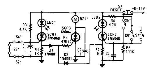
A straightforward high-power alarm driver electronic project can be developed using this circuit diagram. This high-power alarm driver project utilizes a low-power SCR to trigger a high-power SCR. When switches S2, S3, or S4 are opened or switches S5, S6,...

varying brightness ac lamp
In this circuit, an SCR is utilized to gradually adjust the brightness of a 120-volt light bulb by regulating the duration for which the AC line voltage is supplied to the lamp during each half-cycle.
This circuit employs a Silicon Controlled...

Simple and practical power SCR trigger circuit diagram
The presentation of a general power thyristor trigger circuit is more complex, and some components are difficult to procure. A successful trigger circuit has been constructed for only a few dollars. This circuit is designed to trigger a thyristor module...

High voltage speed optocoupler and application circuit diagram
The technical parameters of high-speed optocouplers include a rise time (t1) of less than or equal to 300 ns, a circuit transfer ratio (CTR) of 50%, an isolation voltage (VSO) of at least 15,000 V, and an output transistor reverse...