


On-off controller
#on-off controller
#solid-state
#triac
#AC line-operated
#timer
#transistor
#load switching
#programmable

Description: The AC line-operated on/off controller is a straightforward and dependable solid-state alternative to a motor-driven cam switch. Time intervals 1 and 2 are programmed using diodes to be 8 hours and 20 hours, respectively. The TIM1 output is buffered by a transistor to provide gate current to a triac, which controls the output load. When power is applied to the circuit, the output load is activated for 8 hours and then deactivated for 20 hours in a continuous cycle.
This AC line-operated on/off controller circuit utilizes a triac as the main switching element, allowing for efficient control of AC loads. The circuit's operation begins when power is supplied, initiating the timing sequence. The timing is managed by two diodes that establish the intervals of 8 hours and 20 hours. The first interval (8 hours) is defined by the charging and discharging of a timing capacitor, which is controlled through a resistor network to set the desired time period.
During the first time interval, the output load is energized, allowing current to flow through the triac. A transistor acts as a buffer for the TIM1 output, ensuring that sufficient gate current is supplied to the triac, facilitating its conduction. The triac remains in the 'on' state for the duration of the 8-hour period.
Once the 8 hours elapse, the circuit transitions to the second time interval, where the output load is turned off for 20 hours. This is accomplished by discharging the timing capacitor, which results in the transistor ceasing to provide gate current to the triac, thereby interrupting the current flow to the load. The cycle then repeats, providing a reliable on/off control for the load with minimal mechanical wear, as there are no moving parts involved.
This design is particularly advantageous for applications requiring timed control of electrical devices, such as lighting systems or industrial equipment, where prolonged operation and energy savings are essential. The solid-state nature of the circuit enhances durability and reduces maintenance needs compared to traditional mechanical switches.The ac line-operated on/off controller is a simple, reliable solid-state alternative to a motive driven cam switch. Time 1 and time 2 are programmed by diodes to be 8 hours and 20 hours respectively. The TIM1 output is buffered by a transistor to supply gate current to a triac which switches the output load
When power is applied to the circuit, the output load is switched on for 8 hours then off for 20 hours repeatedly.
This AC line-operated on/off controller circuit utilizes a triac as the main switching element, allowing for efficient control of AC loads. The circuit's operation begins when power is supplied, initiating the timing sequence. The timing is managed by two diodes that establish the intervals of 8 hours and 20 hours. The first interval (8 hours) is defined by the charging and discharging of a timing capacitor, which is controlled through a resistor network to set the desired time period.
During the first time interval, the output load is energized, allowing current to flow through the triac. A transistor acts as a buffer for the TIM1 output, ensuring that sufficient gate current is supplied to the triac, facilitating its conduction. The triac remains in the 'on' state for the duration of the 8-hour period.
Once the 8 hours elapse, the circuit transitions to the second time interval, where the output load is turned off for 20 hours. This is accomplished by discharging the timing capacitor, which results in the transistor ceasing to provide gate current to the triac, thereby interrupting the current flow to the load. The cycle then repeats, providing a reliable on/off control for the load with minimal mechanical wear, as there are no moving parts involved.
This design is particularly advantageous for applications requiring timed control of electrical devices, such as lighting systems or industrial equipment, where prolonged operation and energy savings are essential. The solid-state nature of the circuit enhances durability and reduces maintenance needs compared to traditional mechanical switches.The ac line-operated on/off controller is a simple, reliable solid-state alternative to a motive driven cam switch. Time 1 and time 2 are programmed by diodes to be 8 hours and 20 hours respectively. The TIM1 output is buffered by a transistor to supply gate current to a triac which switches the output load
When power is applied to the circuit, the output load is switched on for 8 hours then off for 20 hours repeatedly.
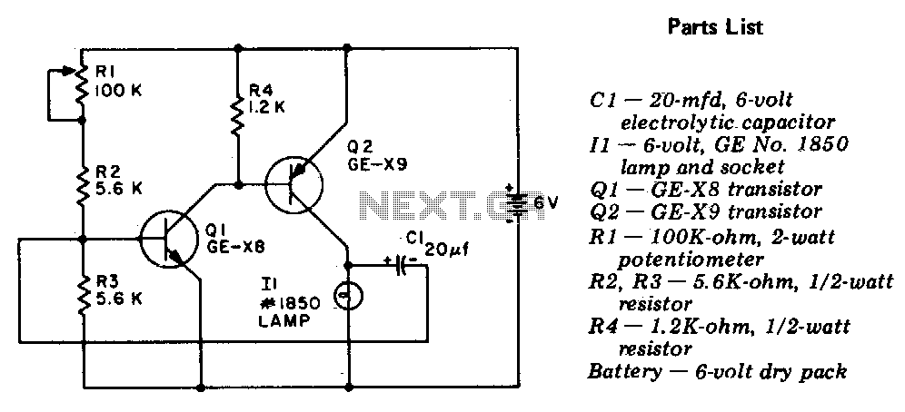
Flasher-light control
The circuit is a two-stage, direct-coupled transistor amplifier configured as a free-running multivibrator. Both the flash duration and flash interval can be adjusted by turning the potentiometer, R1.
The described circuit operates as a two-stage, direct-coupled transistor amplifier, functioning as a...

2 channel audio mixer circuit using transistors
This two-channel audio mixer utilizes 2N3904 transistors to create two preamplifiers. The first preamplifier is designed for high gain, suitable for microphone input, while the second preamplifier allows for control over the audio level input. The audio mixer requires a...

DC Control for Triacs
A relay is an effective solution for switching a mains voltage circuit, particularly in applications where long switching times and high currents are present. However, a...
A relay is an electromechanical switch that uses an electromagnetic coil to control the opening...

modified battery charger circuit
Using a transistor will not yield accurate results, and the adjustment process can become quite tedious. The circuit is technically correct; if the tripping point can be adjusted properly, it may function as intended. Vinod states that he created a...

100w inverter circuit
This is a 100-watt transistor inverter circuit diagram that features a straightforward design. The circuit utilizes only transistors, eliminating the need for integrated circuits. It converts a 12V battery input into a 220V output with a 50Hz square wave signal....
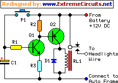
car headlights timer schematics
This device functions as a simple timer that keeps the vehicle's headlights on for approximately 1 minute and 30 seconds, allowing access to dark areas without the need to return and switch off the lights. Pressing switch P1 enables capacitor...

capacitor Choosing components for a triacs snubber
Interfacing the BT139-600 TRIAC with the MOC3051-M Opto-triac requires the construction of a snubber circuit as illustrated in the MOC3051M opto-triac's datasheet on page 8, figure 12. The load connected to this circuit will be a 230V AC, 4A motor....

Simple Alarm Circuit
The simple circuit generates an audible alarm notification, functioning as a burglar alarm utilizing five transistors.
This circuit operates as a basic burglar alarm system designed to emit an audible sound when triggered. The core component of the circuit is a...

Ship Navigation lights circuit
The self-excited multivibrator circuit utilizes transistors VTi and VT2 to generate an output signal that triggers a thyristor (VT3). An adjustment potentiometer (RP) is incorporated to modify the oscillation frequency, which in turn adjusts the flashing cycles of lights Hi...