


Totem-pole-driver-with-bootstrapping
#totem-pole
#bootstrapping
#MOSPOWER
#gate voltage
#driver circuit
#high-voltage
#bootstrap capacitors
#diode OR gates

Description: When driving MOSPOWER in a totem-pole output configuration, it is essential to maintain a gate voltage of 10 to 15 V positive relative to the source to manage load currents close to the maximum ratings of the MOSPOWER device. The D169 component is suitable for bootstrapping due to its high-voltage ratings. In the illustrated circuit, the voltage across the 2000-pF bootstrap capacitors is applied to the V+ terminal through diode OR gates. Consequently, irrespective of which output is in a high state, 30 V is present at V+. The maximum switching frequency is influenced by the input capacitance of the MOSPOWER transistors utilized.
The described circuit involves a totem-pole output configuration, which is commonly used in applications requiring efficient driving of MOSPOWER devices. In this arrangement, the gate of the MOSFET must receive a sufficiently high voltage to ensure that it remains in the enhancement mode and can effectively handle the load currents without entering the triode region, which could lead to excessive power dissipation.
The D169 component, noted for its high-voltage capabilities, allows for an effective bootstrapping technique. Bootstrapping is a method that enhances the gate drive voltage above the supply voltage, enabling better switching performance and minimizing losses. In this circuit, the bootstrap capacitors, rated at 2000 pF, are charged to a voltage level that can be utilized to ensure that the gate voltage remains sufficiently high, even under varying load conditions.
Diode OR gates are employed to facilitate the connection of the bootstrap capacitors to the V+ terminal. This configuration ensures that regardless of which output is active, the circuit maintains a constant voltage level of 30 V at the V+ terminal. This voltage is crucial for the reliable operation of the MOSPOWER devices, particularly when switching at high frequencies.
The maximum switching frequency of the circuit is primarily governed by the input capacitance of the MOSPOWER transistors. Higher input capacitance can lead to slower switching speeds due to the increased time required to charge and discharge the gate capacitance. Therefore, selecting MOSPOWER transistors with optimal input capacitance is critical for achieving the desired switching frequency while maintaining efficient operation.
In summary, the circuit design effectively utilizes bootstrapping techniques alongside diode OR gates to maintain a high gate voltage for MOSPOWER devices in totem-pole output configurations, ensuring optimal performance and reliability in high-frequency applications.When driving MOSPOWER in a totem-pole output configuration, it is necessary to have the gate voltage 10 to 15 V positive with respect to the source in order to handle load currents near the MOSPOWER maximum ratings. The D169 lends itself to bootstrapping because of its high-voltage ratings. In the circuit shown, the voltage on the 2000-pF bootstrap capacitors is applied via diode OR gates to the V + terminal.
Therefore, regardless of which output is high, 30 Vis present at V + . Maximum switching frequency is determined by the input capacitance of the MOSPOWER transistors used.
The described circuit involves a totem-pole output configuration, which is commonly used in applications requiring efficient driving of MOSPOWER devices. In this arrangement, the gate of the MOSFET must receive a sufficiently high voltage to ensure that it remains in the enhancement mode and can effectively handle the load currents without entering the triode region, which could lead to excessive power dissipation.
The D169 component, noted for its high-voltage capabilities, allows for an effective bootstrapping technique. Bootstrapping is a method that enhances the gate drive voltage above the supply voltage, enabling better switching performance and minimizing losses. In this circuit, the bootstrap capacitors, rated at 2000 pF, are charged to a voltage level that can be utilized to ensure that the gate voltage remains sufficiently high, even under varying load conditions.
Diode OR gates are employed to facilitate the connection of the bootstrap capacitors to the V+ terminal. This configuration ensures that regardless of which output is active, the circuit maintains a constant voltage level of 30 V at the V+ terminal. This voltage is crucial for the reliable operation of the MOSPOWER devices, particularly when switching at high frequencies.
The maximum switching frequency of the circuit is primarily governed by the input capacitance of the MOSPOWER transistors. Higher input capacitance can lead to slower switching speeds due to the increased time required to charge and discharge the gate capacitance. Therefore, selecting MOSPOWER transistors with optimal input capacitance is critical for achieving the desired switching frequency while maintaining efficient operation.
In summary, the circuit design effectively utilizes bootstrapping techniques alongside diode OR gates to maintain a high gate voltage for MOSPOWER devices in totem-pole output configurations, ensuring optimal performance and reliability in high-frequency applications.When driving MOSPOWER in a totem-pole output configuration, it is necessary to have the gate voltage 10 to 15 V positive with respect to the source in order to handle load currents near the MOSPOWER maximum ratings. The D169 lends itself to bootstrapping because of its high-voltage ratings. In the circuit shown, the voltage on the 2000-pF bootstrap capacitors is applied via diode OR gates to the V + terminal.
Therefore, regardless of which output is high, 30 Vis present at V + . Maximum switching frequency is determined by the input capacitance of the MOSPOWER transistors used.

Positive High-Voltage Hot Swap Controller with Power Limiter
This is a positive high-voltage hot swap controller circuit with a power limiter. This circuit utilizes the TPS2491 or TPS2490, as both of them have specific features.
The positive high-voltage hot swap controller circuit is designed to safely connect and disconnect...

High-voltage-regulator
The regulator provides a 100 V output at 100 mA and can withstand shorts to ground. Even at a 100 V output, the LT317A operates in normal mode, maintaining a 1.2 V difference between its output and adjustment pin. Under...

Solid-state electric fence charger
A touch-sensing circuit maintains the high-voltage generator in an off state until contact is made with the fence wire. When something touches the fence sensing circuit wire, it activates the high-voltage generator, which delivers a series of 500-microsecond pulses at...

Battery-powered-high-voltage-generator
An output voltage sufficient to bridge a one-inch gap can be generated from a 12-V power source. A 555 timer integrated circuit (IC) is configured as an astable multivibrator, producing a narrow negative pulse at pin 3. This pulse activates...

Cable bootstrapping
A bootstrapping input shield for a follower reduces cable capacitance, leakage, and spurious voltages resulting from cable flexing. Instability can be mitigated by using a small capacitor on the input.
The bootstrapping input shield is a critical component in electronic circuits...
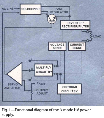
Heavy-duty power supply regulates either voltage current or power
By combining switching and series-pass techniques, the designer of this high-voltage supply achieved 0.01% regulation at power levels up to 100W.
The high-voltage power supply employs a hybrid approach that integrates both switching and series-pass regulation methods to achieve exceptional performance....

Simple-high-voltage-supply
This circuit generates high-voltage pulses using an inexpensive auto ignition coil. By adding a rectifier to the output, the circuit produces high-voltage direct current (DC). The input to the circuit is 115 Vac. During the positive half cycle of the...

Electrification Circuit Unit
This circuit design is intended for conducting harmless experiments with high-voltage pulses, functioning similarly to an electrified fence generator. The pulse repetition frequency (PRF) is determined by the time constant of the resistor-capacitor network R1-C3 in the feedback loop of...
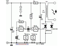
Simple Electrification Unit
The circuit is designed for conducting safe experiments with high-voltage pulses and operates similarly to an electrified fence generator.
This circuit is engineered to generate high-voltage pulses suitable for educational purposes and experimentation. The design is inspired by electrified fence generators,...