


Cellular Phone calling Detector
#cellular phone
#detector
#sensor coil
#LED
#transistor
#monostable
#ultra-bright LED
#field detection
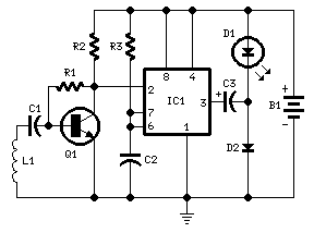
Description: This circuit was designed to detect when a call is incoming in a cellular phone (even when the calling tone of the device is switched-off) by means of a flashing LED. The device must be placed a few centimeters from the cellular phone, so its sensor coil L1 can detect the field emitted by the phone receiver during an incoming call. The signal detected by the sensor coil is amplified by transistor Q1 and drives the monostable input pin of IC1. The IC's output voltage is doubled by C2 & D2 in order to drive the high-efficiency ultra-bright LED at a suitable peak-voltage. Stand-by current drawing is less than 200µA, therefore a power on/off switch is unnecessary. Sensitivity of this circuit depends on the sensor coil type. L1 can be made by winding 130 to 150 turns of 0.2 mm enameled wire on a 5 cm diameter former (e.g. a can).
This circuit operates on the principle of electromagnetic induction to detect the RF signal emitted by a cellular phone during an incoming call. The sensor coil, L1, is critical to the circuit's functionality. By winding 130 to 150 turns of 0.2 mm enameled wire around a 5 cm diameter former, the coil is able to capture the low-frequency electromagnetic fields generated by the phone. The placement of the circuit near the phone is essential, as the sensitivity of the detection is directly related to the proximity of the sensor to the phone's receiver.
Once the signal is detected by L1, it is fed into transistor Q1, which serves as an amplifier. This transistor is configured in a common-emitter arrangement, allowing it to amplify the weak signal from the coil. The amplified output from Q1 is then connected to the monostable input pin of the integrated circuit IC1, which is typically a timer IC such as the 555 timer. The monostable configuration allows the IC to produce a single output pulse when triggered by the incoming signal, which is essential for driving the LED.
The output from IC1 is then processed by a voltage doubling circuit composed of capacitor C2 and diode D2. This stage is crucial for ensuring that the output voltage is sufficient to drive the ultra-bright LED. The LED is chosen for its high efficiency and brightness, ensuring that the visual indication of an incoming call is prominent even in bright ambient light conditions.
The design of this circuit emphasizes low power consumption, with a standby current draw of less than 200µA. This allows for continuous operation without the need for a power switch, making it convenient for users. The overall effectiveness of the circuit can be influenced by the choice of components, particularly the sensor coil, which must be tailored to the specific application and environment in which the circuit operates.This circuit was designed to detect when a call is incoming in a cellular phone (even when the calling tone of the device is switched-off) by means of a flashing LED. The device must be placed a few centimeters from the cellular phone, so its sensor coil L1 can detect the field emitted by the phone receiver during an incoming call.
The signal detected by the sensor coil is amplified by transistor Q1 and drives the monostable input pin of IC1. The IC`s output voltage is doubled by C2 & D2 in order to drive the high-efficiency ultra-bright LED at a suitable peak-voltage.
# Stand-by current drawing is less than 200µA, therefore a power on/off switch is unnecessary. Sensitivity of this circuit depends on the sensor coil type. L1 can be made by winding 130 to 150 turns of 0.2 mm. enameled wire on a 5 cm. diameter former (e.g. a can).
This circuit operates on the principle of electromagnetic induction to detect the RF signal emitted by a cellular phone during an incoming call. The sensor coil, L1, is critical to the circuit's functionality. By winding 130 to 150 turns of 0.2 mm enameled wire around a 5 cm diameter former, the coil is able to capture the low-frequency electromagnetic fields generated by the phone. The placement of the circuit near the phone is essential, as the sensitivity of the detection is directly related to the proximity of the sensor to the phone's receiver.
Once the signal is detected by L1, it is fed into transistor Q1, which serves as an amplifier. This transistor is configured in a common-emitter arrangement, allowing it to amplify the weak signal from the coil. The amplified output from Q1 is then connected to the monostable input pin of the integrated circuit IC1, which is typically a timer IC such as the 555 timer. The monostable configuration allows the IC to produce a single output pulse when triggered by the incoming signal, which is essential for driving the LED.
The output from IC1 is then processed by a voltage doubling circuit composed of capacitor C2 and diode D2. This stage is crucial for ensuring that the output voltage is sufficient to drive the ultra-bright LED. The LED is chosen for its high efficiency and brightness, ensuring that the visual indication of an incoming call is prominent even in bright ambient light conditions.
The design of this circuit emphasizes low power consumption, with a standby current draw of less than 200µA. This allows for continuous operation without the need for a power switch, making it convenient for users. The overall effectiveness of the circuit can be influenced by the choice of components, particularly the sensor coil, which must be tailored to the specific application and environment in which the circuit operates.This circuit was designed to detect when a call is incoming in a cellular phone (even when the calling tone of the device is switched-off) by means of a flashing LED. The device must be placed a few centimeters from the cellular phone, so its sensor coil L1 can detect the field emitted by the phone receiver during an incoming call.
The signal detected by the sensor coil is amplified by transistor Q1 and drives the monostable input pin of IC1. The IC`s output voltage is doubled by C2 & D2 in order to drive the high-efficiency ultra-bright LED at a suitable peak-voltage.
# Stand-by current drawing is less than 200µA, therefore a power on/off switch is unnecessary. Sensitivity of this circuit depends on the sensor coil type. L1 can be made by winding 130 to 150 turns of 0.2 mm. enameled wire on a 5 cm. diameter former (e.g. a can).

Audiostrobe-compatible LED glasses
Audiostrobe glasses are utilized alongside light and sound machines, as well as certain brainwave entrainment software. The glasses are equipped with built-in LEDs.
Audiostrobe glasses are designed to enhance the sensory experience provided by light and sound machines, which are often...
Steady flow of power transistor circuit
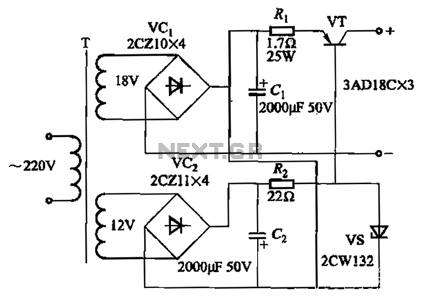
Characterized by a steady flow of power when the power supply voltage fluctuates or the load changes, this circuit maintains a constant load current. The output current of the circuit is illustrated in Figure 4A. When the load varies from...

Thrifty LED Protector
An LED will fail if the current flowing through it is excessively high. This issue can be easily resolved by incorporating a simple resistor in series, which is an effective and low-cost solution. However, as the power supply voltage increases,...

Mains Voltage Indicator with a LED
A need exists for a 220V AC line light display or main voltage monitor due to frequent electrical issues in a home.
To create a 220V AC line light display or voltage monitor, a circuit can be designed using a combination...

simplest mains operated led flasher
The following mains-operated LED flasher circuit, which is essentially an astable multivibrator circuit, utilizes a diac and resistor arrangement to achieve an interesting wig-wag flashing effect with two LEDs. The circuit was shared by Mr. Vineesh, a dedicated follower of...
Transistor sorter-tester
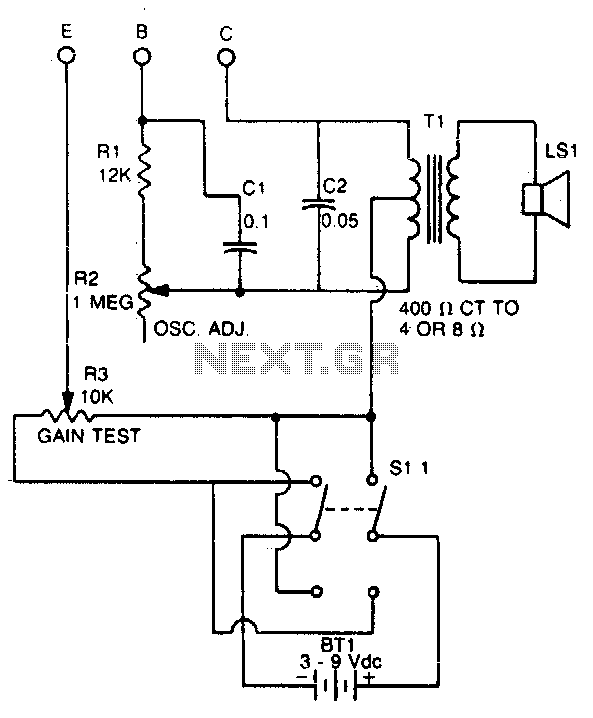
This tester checks the polarity of transistors (PNP or NPN). An audible signal indicates the gain. Additionally, the tester can function as a GO/NO GO tester for matching unmarked devices.
The transistor tester is designed to evaluate the polarity and gain...

kode kunci satu transistor
This is the simplest electronic code lock circuit that can be constructed. The circuit utilizes one transistor, a relay, and a few passive components. Its simplicity does not compromise performance, as the circuit operates effectively. Essentially, it functions as a...

Mini Logic probe with transistor circuit
This logic probe circuit is designed for checking voltage levels in TTL circuits. It receives signals from the circuit being tested and indicates whether the logic level is high or low. When the input voltage at the probe tip exceeds...

Transistor-flasher
This astable multivibrator utilizes incandescent lamps instead of collector load resistors. The lamps flash on and off alternately.
The circuit operates as an astable multivibrator, which is a type of oscillator that continuously switches between its high and low states without...