


Isolated Telephone Interface
#telephone
#isolation
#transformer
#RJ-11
#zener diodes
#ringing signal
#tape recorder
#potentiometer
#capacitor

Description: There's not much to this circuit. The two RJ-11 jacks are set up to feed the telephone circuit through from the wall to the phone. The active signal for a single phone is on the red and green wires. Yellow and black are usually used for a second phone line. The 0.22uF capacitor blocks any DC current from flowing through the transformer. The 4.7K resistor limits the current of the 90V ringing signal. The transformer isolates the telephone side of the circuit from the tape recorder side. The zener diodes clamp the 90 volt ringing signal and other transient spikes to protect your recorder. The 10K potentiometer is used to adjust the level to the tape recorder.
This circuit serves as a basic telephone interface that connects a standard telephone line to a tape recorder for recording phone conversations. It utilizes RJ-11 jacks, which are industry-standard connectors for telephone wiring. The circuit is designed to handle both the audio signal and the ringing voltage from the telephone line.
The red and green wires from the RJ-11 jacks carry the audio signal for a single phone line, while the yellow and black wires are typically reserved for a second line. The inclusion of a 0.22 microfarad capacitor is crucial as it blocks any DC component from the telephone line, ensuring that only the AC audio signals pass through to the transformer. This is important for protecting sensitive audio equipment, such as the tape recorder.
The transformer plays a vital role in this circuit, providing electrical isolation between the telephone line and the tape recorder. This isolation helps to prevent any potential damage to the recorder from high voltages present on the telephone line, particularly during ringing signals. The transformer also allows for impedance matching, which can improve the quality of the audio signal being recorded.
A 4.7K ohm resistor is incorporated into the circuit to limit the current of the 90V ringing signal. This is a protective measure to ensure that the high voltage does not exceed safe levels for the downstream components, particularly the tape recorder.
Zener diodes are used to clamp the ringing voltage and protect the tape recorder from transient voltage spikes. These diodes will conduct when the voltage exceeds a certain threshold, thereby shunting excess voltage away from sensitive components and preventing damage.
Finally, a 10K ohm potentiometer is included in the circuit to allow for level adjustment of the audio signal being fed into the tape recorder. This feature enables the user to optimize the recording level based on the specific requirements of the tape recorder and the volume of the incoming audio signal.
Overall, this circuit is a straightforward yet effective solution for interfacing a telephone line with a recording device, ensuring both functionality and protection for the equipment involved.There`s not much to this circuit. The two RJ-11 jacks are set up to feed the telephone circuit through from the wall to the phone. The active signal for a single phone is on the red and green wires. Yellow and black are usually used for a second phone line. The 0.22uF capacitor blocks any DC current from flowing through the transformer. The 4.7K resistor limits the current of the 90V ringing signal. The transformer isolates the telephone side of the circuit from the tape recorder side. The zener diodes clamp the 90 volt ringing signal and other transient spikes to protect your recorder. The 10K potentiometer is used to adjust the level to the tape recorder.
This circuit serves as a basic telephone interface that connects a standard telephone line to a tape recorder for recording phone conversations. It utilizes RJ-11 jacks, which are industry-standard connectors for telephone wiring. The circuit is designed to handle both the audio signal and the ringing voltage from the telephone line.
The red and green wires from the RJ-11 jacks carry the audio signal for a single phone line, while the yellow and black wires are typically reserved for a second line. The inclusion of a 0.22 microfarad capacitor is crucial as it blocks any DC component from the telephone line, ensuring that only the AC audio signals pass through to the transformer. This is important for protecting sensitive audio equipment, such as the tape recorder.
The transformer plays a vital role in this circuit, providing electrical isolation between the telephone line and the tape recorder. This isolation helps to prevent any potential damage to the recorder from high voltages present on the telephone line, particularly during ringing signals. The transformer also allows for impedance matching, which can improve the quality of the audio signal being recorded.
A 4.7K ohm resistor is incorporated into the circuit to limit the current of the 90V ringing signal. This is a protective measure to ensure that the high voltage does not exceed safe levels for the downstream components, particularly the tape recorder.
Zener diodes are used to clamp the ringing voltage and protect the tape recorder from transient voltage spikes. These diodes will conduct when the voltage exceeds a certain threshold, thereby shunting excess voltage away from sensitive components and preventing damage.
Finally, a 10K ohm potentiometer is included in the circuit to allow for level adjustment of the audio signal being fed into the tape recorder. This feature enables the user to optimize the recording level based on the specific requirements of the tape recorder and the volume of the incoming audio signal.
Overall, this circuit is a straightforward yet effective solution for interfacing a telephone line with a recording device, ensuring both functionality and protection for the equipment involved.There`s not much to this circuit. The two RJ-11 jacks are set up to feed the telephone circuit through from the wall to the phone. The active signal for a single phone is on the red and green wires. Yellow and black are usually used for a second phone line. The 0.22uF capacitor blocks any DC current from flowing through the transformer. The 4.7K resistor limits the current of the 90V ringing signal. The transformer isolates the telephone side of the circuit from the tape recorder side. The zener diodes clamp the 90 volt ringing signal and other transient spikes to protect your recorder. The 10K potentiometer is used to adjust the level to the tape recorder.

transformer Low voltage oscillator for joule thief
A transformer with two input leads and three output leads was used. An LED was connected to two of the output leads, and when a dead AA battery was connected to the input leads, the LED blinked for a brief...
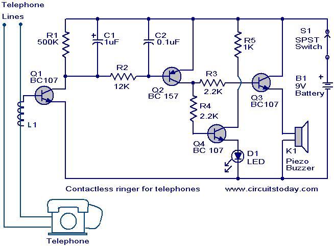
Contactless telephone ringer circuit
The contactless telephone ringer circuit is designed to produce an audible ring and a visual indication when a call is received. Its primary advantage lies in the absence of direct contact between the telephone line and the circuit, which eliminates...

telephone in use indicator
It is illegal to create a permanent physical connection to telephone lines in certain countries, including the UK and Ireland. When constructing this circuit, it is advisable to utilize a plug-in cord to allow for disconnection in the event of...

High isolation telephone ringer
The diode rectifies the ringing signal to provide operating power to the audio relaxation oscillator, which consists of L1, L2, R1, R2, and C. Additionally, L2, in conjunction with Q1, functions as an opto-isolator, effectively isolating the telephone line from...

Telephone electronic coded lock circuit
The telephone electronic coded lock circuit is designed for double audio circuits. When this coded lock is installed on a phone, dialing out requires the user to input a four-digit pre-programmed password using the phone's buttons. If the password entered...

Multi-output power supply circuit
This document presents a multi-output power supply circuit. The circuit utilizes the secondary winding of a transformer and incorporates four voltage regulators: 7812, 7805, 7905, and 7912, providing independent output voltages of +12V, +5V, -5V, and -12V, respectively. Each output...

Multipurpose Circuit for telephone
Multipurpose circuit for telephone. This add-on device for telephones can be connected in parallel to the telephone instrument. The circuit provides audio-visual indication of on-hook.
This multipurpose circuit serves as an enhancement for standard telephone systems by providing both audio and...
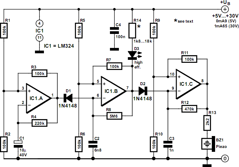
schematics electronic telephone ringer
This circuit generates a ringing sound similar to that produced by modern telephones. It comprises three nearly identical oscillators connected in a series configuration, each generating a square wave signal. The frequency of each oscillator is determined by the RC...

power supply am farm radio
The ability accumulation is a Tamura 3FD-410 5V bifold primary/dual accessory transformer, available from DigiKey.com at reasonable prices. The transformer's primary windings can be configured in series for 240VAC operation or in parallel for 120VAC operation. This configuration utilizes one...