


Ringer-relay

Description: When the phone rings, the ring signal from the telephone company activates a neon lamp within a CLM3120 optocoupler. This activation results in a decrease in the resistance of the CdS cell output of the device, which in turn switches on transistor Q1. As Q1 turns on, relay K1 is energized. The circuit should be connected in series with the lamp that is to be activated.
The described circuit utilizes a CLM3120 optocoupler to isolate the telephone line from the control circuit, ensuring that high voltages present in the telephone line do not affect the low-voltage components of the activation circuit. The neon lamp serves as an indicator and a triggering mechanism that responds to the ringing signal from the telephone line.
When the telephone rings, the alternating current (AC) signal causes the neon lamp to illuminate. The neon lamp’s illumination indicates that the optocoupler is triggered, which causes a significant drop in the resistance of the CdS (cadmium sulfide) cell. This change in resistance is critical as it allows for a sufficient current to flow through the base of transistor Q1, turning it on.
Once Q1 is activated, it allows current to flow through the relay coil of K1. The relay acts as a switch, enabling it to control higher power circuits, such as lamps or other appliances, that are connected in series with the relay's contacts. This configuration ensures that when the phone rings, the relay closes, completing the circuit and energizing the connected lamp.
It is essential to select the appropriate relay based on the load requirements of the lamp, including its voltage and current ratings. Additionally, the circuit should incorporate necessary protective components, such as diodes across the relay coil, to prevent back EMF from damaging the transistor when the relay is de-energized. Proper design considerations must also include the ratings of the neon lamp and the CdS cell to ensure reliable operation under varying conditions. The overall design provides a simple yet effective solution for activating a lamp in response to an incoming phone call.When the phone rings, the ring signal from the telephone company lights a neon lamp within a CLM3120 optocoupler. That causes a drop in the resistance of the CdS cell output of the device, turning on transistor Ql.
When Ql turns on, relay Kl is energized. The circuit should be connected in series with the lamp that is to be activated.
The described circuit utilizes a CLM3120 optocoupler to isolate the telephone line from the control circuit, ensuring that high voltages present in the telephone line do not affect the low-voltage components of the activation circuit. The neon lamp serves as an indicator and a triggering mechanism that responds to the ringing signal from the telephone line.
When the telephone rings, the alternating current (AC) signal causes the neon lamp to illuminate. The neon lamp’s illumination indicates that the optocoupler is triggered, which causes a significant drop in the resistance of the CdS (cadmium sulfide) cell. This change in resistance is critical as it allows for a sufficient current to flow through the base of transistor Q1, turning it on.
Once Q1 is activated, it allows current to flow through the relay coil of K1. The relay acts as a switch, enabling it to control higher power circuits, such as lamps or other appliances, that are connected in series with the relay's contacts. This configuration ensures that when the phone rings, the relay closes, completing the circuit and energizing the connected lamp.
It is essential to select the appropriate relay based on the load requirements of the lamp, including its voltage and current ratings. Additionally, the circuit should incorporate necessary protective components, such as diodes across the relay coil, to prevent back EMF from damaging the transistor when the relay is de-energized. Proper design considerations must also include the ratings of the neon lamp and the CdS cell to ensure reliable operation under varying conditions. The overall design provides a simple yet effective solution for activating a lamp in response to an incoming phone call.When the phone rings, the ring signal from the telephone company lights a neon lamp within a CLM3120 optocoupler. That causes a drop in the resistance of the CdS cell output of the device, turning on transistor Ql.
When Ql turns on, relay Kl is energized. The circuit should be connected in series with the lamp that is to be activated.

Amplifier input signal overdrive auto-protection
That circuit protects the overdriven signals going into an amplifier. Instead of a zener diode, we use a transistor. That way we ensure that the above the ordinary input voltages (1 volt r.m.s.) can be achieved without distortion. Also, the...

Video amplifier splitter by transistor BD137-BC547-BC557
This is a video amplifier circuit or video splitter circuit, designed to strengthen video signals. It compensates for signal loss and is...
The video amplifier circuit serves as a crucial component in video signal distribution systems, ensuring that the integrity and...

Telephone Silencer
If a user is busy and cannot answer or does not wish to answer their phone, this circuit will emit a busy signal without requiring the phone to be left off the hook. After a predetermined duration, the circuit automatically...

Series-telephone-connection
A straightforward method of connecting in series within a telephone set is suitable for PABX or short line applications. When the telephone handset is lifted, capacitor C1 is charged through diode D1 to (Vz1 - 0.7) V, initiating a DF320...

Economical Transistor Radio
The schematic diagram illustrates an audio stage utilizing a common-collector circuit. This configuration does not dampen the tuned circuit; rather, it enhances its response, resulting in improved sensitivity and selectivity. Due to the low supply voltage, the subsequent audio amplifier...
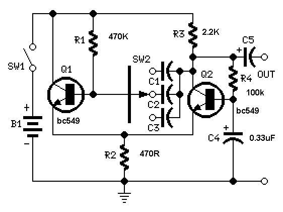
Simple Square wave Generator using transistors ~ Easy Electronics
A useful feature of this circuit is that the frequency can be changed by modifying the capacitor value. A switch can be added to select between various frequencies.
This circuit utilizes a capacitor in conjunction with an oscillator to determine its...

Alternating current voltage amplifier transistor
An alternating current voltage amplifier transistor AC path is described. In AC analysis, the internal resistance of the AC supply voltage source is low, which corresponds to a short circuit signal. Consequently, the alternating voltage terminal Vcc is considered to...

One transistor audio mixer (2N3563)
This circuit mixer features internal amplification using a 2N3563 transistor. Two input signals can be independently adjusted via VRI and VR2. The VR3 balance control allows for the attenuation of one signal while the other remains active. Additionally, the transistor...

Programmable multi-tone telephone ringer
Two BST72 transistors provide an output voltage swing almost equal to the voltage at C3. Pins IS1 and IS2 are inoperative because DM = HIGH. Volume control is possible using resistor Rv.
The circuit utilizes two BST72 transistors configured to amplify...