


Simple home telephone ringtone generator circuit using CD4060B
#CD4060B
#ringtone generator
#intercom
#telephone
#audio signal
#oscillator
#DC supply
#home automation
#simple circuit

Description: This is a simple home telephone ringtone generator circuit constructed using only a few electronic components. It generates a simulated telephone ringtone and requires a DC supply voltage ranging from 4.5V to 12V. This circuit can be used in standard intercom systems or phone-type intercoms. The sound produced is notably loud when operating on a +12V DC power supply, and the volume of the ringtone can be adjusted. The circuit employs a 14-stage binary ripple counter with a built-in oscillator (CMOS IC CD4060 B) to create three different pulse outputs from pin 1 (O11), pin 3 (O13), and pin 14 (O7). Preset VR1 is calibrated to generate 0.3125Hz pulses (1.6 seconds low followed by 1.6 seconds high) at pin 3 of IC1. The pulse output from pin 1 provides a frequency of 1.25Hz (0.4 seconds low, 0.4 seconds high), and pin 14 produces a 20Hz output. These three output pins of IC1 are connected to the base terminals of transistors T1, T2, and T3 through resistors R1, R2, and R3, respectively. The transistors are arranged in such a manner that the positive voltage at the emitter of T1 is extended to the collector of T3 when all three outputs are low. Consequently, T1, T2, and T3 are forward biased for 0.4, 1.6, and 0.025 seconds, respectively, and reverse biased for the same durations. A built-in oscillator-type piezo buzzer generates a tone of approximately 1kHz. In this circuit, the piezo buzzer is activated and deactivated at a frequency of 20Hz to produce the ringtone sound via transistor T3. The 20Hz pulses are available at the collector of T3 for a duration of 0.4 seconds, followed by a silent interval of 2 seconds. This pulse pattern repeats continuously. Additionally, preset VR2 can be used to adjust the amplitude of the ringtone.
The circuit utilizes the CMOS IC CD4060 B, which is a versatile binary ripple counter and oscillator. This IC is key to generating the necessary pulse frequencies that drive the transistors and ultimately the piezo buzzer. The three output frequencies allow for the creation of a distinctive ringtone that mimics traditional telephone sounds.
Transistors T1, T2, and T3 serve as amplifiers and switches in this configuration. When the output from the IC is low, the transistors are turned off, and when the output is high, they allow current to flow through, thus activating the piezo buzzer. The resistors R1, R2, and R3 are crucial for limiting the base current to the transistors, ensuring they operate within safe limits while providing sufficient gain.
The piezo buzzer, characterized by its simplicity and efficiency, is driven by the pulsed output from T3. The activation at 20Hz creates an audible ringtone, while the silent intervals help in distinguishing the ringtone pattern. The adjustable presets (VR1 and VR2) provide flexibility in tuning the frequency and amplitude of the output sound, allowing customization based on user preference or specific application requirements.
The circuit's design is compact and efficient, making it suitable for integration into various intercom systems or standalone applications where a simple ringtone generator is required. The use of commonly available components ensures ease of assembly and repair, making this circuit an excellent choice for hobbyists and professionals alike.This is a simple home telephone ringtone generator circuit which is built with applying only several electronic components / parts. It generates simulated telephone ringtone and requires only DC supply with 4. 5V DC to 12V DC voltage. One may possibly use this circuit in ordinary intercom or phone-type intercom. The sound is pretty loud when this c ircuit is operated on +12V DC power supply. Even so, the volume of ring sound can be adjusted. The widely available 14-stage binary ripple counter with built-in oscillator (CMOS IC CD4060 B) is chosen to produce three kinds of pulses, that are obtainable from pin 1 (O11), pin 3 (O13), and pin 14 (O7), respectively. Preset VR1 is fine-tuned to get 0. 3125Hz pulses (1. 6 second low` followed by 1. 6-second high`) at pin 3 of IC1. At the same time, pulses obtainable from pin 1 will be of 1. 25 Hz (0. 4-second low`, 0. 4-second high`) and 20 Hz at pin 14. The three output pins of IC1 are connected to base terminals of transistors T1, T2, and T3 through resistors R1, R2, and R3, respectively.
Transistors T1 through T3 are cascaded in this kind of a way that the positive voltage obtainable at the emitter of transistor T1 is extended to the collector of transistor T3 once the outputs of all of the three stages are low. As a result, transistors T1 through T3 are forward biased for 0. 4, 1. 6, and 0. 025 seconds, respectively and reverse biased for similar durations. Working with a built-in oscillator-type piezobuzzer generates about 1kHz tone. In this particular circuit, the piezo-buzzer is turned on` and off` at 20 Hz for ring tone sound by transistor T3.
20Hz pulses are obtainable at the collector of transistor T3 for 0. 4-second duration. Just after a time interval of 0. 4 second, 20Hz pulses become again obtainable for another 0. 4-second duration. This is followed by two seconds of nosound interval. Thereafter the pulse pattern repeats by itself. Refer the figure that signifies waveforms obtainable at several points including the collector of transistor T3. Preset VR2 could be utilized for adjusting the amplitude of the ring tone.
The circuit utilizes the CMOS IC CD4060 B, which is a versatile binary ripple counter and oscillator. This IC is key to generating the necessary pulse frequencies that drive the transistors and ultimately the piezo buzzer. The three output frequencies allow for the creation of a distinctive ringtone that mimics traditional telephone sounds.
Transistors T1, T2, and T3 serve as amplifiers and switches in this configuration. When the output from the IC is low, the transistors are turned off, and when the output is high, they allow current to flow through, thus activating the piezo buzzer. The resistors R1, R2, and R3 are crucial for limiting the base current to the transistors, ensuring they operate within safe limits while providing sufficient gain.
The piezo buzzer, characterized by its simplicity and efficiency, is driven by the pulsed output from T3. The activation at 20Hz creates an audible ringtone, while the silent intervals help in distinguishing the ringtone pattern. The adjustable presets (VR1 and VR2) provide flexibility in tuning the frequency and amplitude of the output sound, allowing customization based on user preference or specific application requirements.
The circuit's design is compact and efficient, making it suitable for integration into various intercom systems or standalone applications where a simple ringtone generator is required. The use of commonly available components ensures ease of assembly and repair, making this circuit an excellent choice for hobbyists and professionals alike.This is a simple home telephone ringtone generator circuit which is built with applying only several electronic components / parts. It generates simulated telephone ringtone and requires only DC supply with 4. 5V DC to 12V DC voltage. One may possibly use this circuit in ordinary intercom or phone-type intercom. The sound is pretty loud when this c ircuit is operated on +12V DC power supply. Even so, the volume of ring sound can be adjusted. The widely available 14-stage binary ripple counter with built-in oscillator (CMOS IC CD4060 B) is chosen to produce three kinds of pulses, that are obtainable from pin 1 (O11), pin 3 (O13), and pin 14 (O7), respectively. Preset VR1 is fine-tuned to get 0. 3125Hz pulses (1. 6 second low` followed by 1. 6-second high`) at pin 3 of IC1. At the same time, pulses obtainable from pin 1 will be of 1. 25 Hz (0. 4-second low`, 0. 4-second high`) and 20 Hz at pin 14. The three output pins of IC1 are connected to base terminals of transistors T1, T2, and T3 through resistors R1, R2, and R3, respectively.
Transistors T1 through T3 are cascaded in this kind of a way that the positive voltage obtainable at the emitter of transistor T1 is extended to the collector of transistor T3 once the outputs of all of the three stages are low. As a result, transistors T1 through T3 are forward biased for 0. 4, 1. 6, and 0. 025 seconds, respectively and reverse biased for similar durations. Working with a built-in oscillator-type piezobuzzer generates about 1kHz tone. In this particular circuit, the piezo-buzzer is turned on` and off` at 20 Hz for ring tone sound by transistor T3.
20Hz pulses are obtainable at the collector of transistor T3 for 0. 4-second duration. Just after a time interval of 0. 4 second, 20Hz pulses become again obtainable for another 0. 4-second duration. This is followed by two seconds of nosound interval. Thereafter the pulse pattern repeats by itself. Refer the figure that signifies waveforms obtainable at several points including the collector of transistor T3. Preset VR2 could be utilized for adjusting the amplitude of the ring tone.
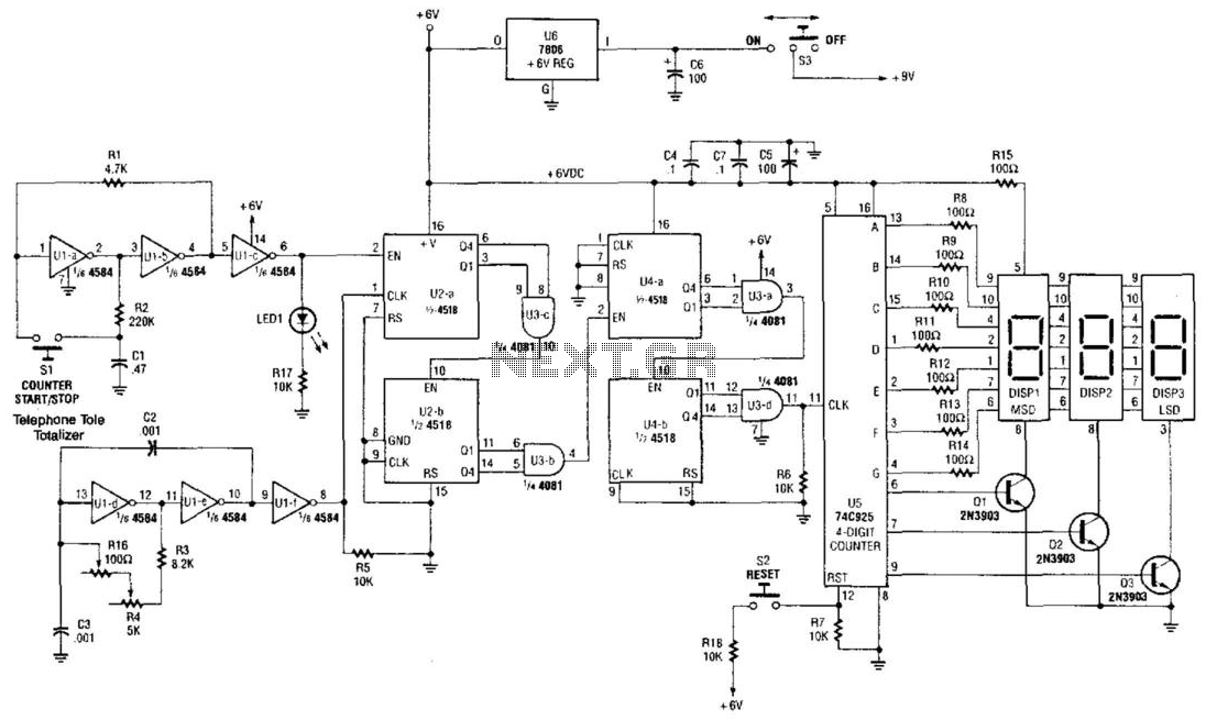
Telephone Toll Totalizer
The Telephone Totalizer is built around two 4518 dual synchronous up counters, a 74C925 4-digit counter, a 458 hex inverting buffer, and a 4081 quad 2-input AND gate. It is designed to estimate toll charges by calculating the time spent...

Telephone Ringer
This circuit generates the sound of the electronic ringer found in modern telephones, replacing the two-bell electromechanical ringers used previously. The ringing pattern adheres to the United States standard of 2 seconds on and 4 seconds off. During the "on"...

Minimal metal detector
This circuit is an oscillator with LI being a 4-inch diameter coil consisting of 35 turns of #26 magnet wire. Metal in proximity to LI will cause the oscillator to shift frequency. An AM transistor radio is used to detect...

Metal detector circuit diagram 8
The metal detector circuit consists of a probe oscillator, a PLL (phase-locked loop) circuit, and an audio alarm circuit. The probe oscillator includes a detection coil (L), transistor (V1), and several resistors (R1 to R3) and capacitors (C1 to C5)....

Micro Power AM Broadcast Transmitter
This circuit utilizes a 74HC14 hex Schmitt trigger inverter as a square wave oscillator to drive a small signal transistor configured in a class C amplifier setup. The frequency of the oscillator can be either fixed using a crystal or...

Safety flare
When the switch SI is activated, power is supplied to an oscillator that consists of Q1, R1, C1, L1, and L2. Coil L1 serves as the primary winding of transformer T1, while L2 functions as the feedback winding. As Q1...

Off Line Telephone Tester
A circuit for an offline telephone tester that does not require a telephone line for testing a telephone instrument. The circuit is simple enough to be assembled by a novice with minimal electronics knowledge. A telephone line can be viewed...

Telephone line monitor circuit
This compact circuit enables automatic recording of phone conversations. It connects to the phone line, the microphone input of a tape recorder, and the remote control jack of the recorder. The circuit detects the voltage level in the phone line...

Vhf-modulator
This circuit utilizes an oscillator (2N2222) and a diode (D1) as a nonlinear mixer. The frequency is determined by a slug in L1. RFCl, C1, and RFC2 create a low-pass filter designed to pass video signals while blocking RF signals...