


Telephone Intercom - DTMF

Description: This version of the Link uses DTMF tones for dialing both internally between handsets, and externally for outside calls. Remember, in some countries, it is ILLEGAL to simply connect unapproved and untested equipment to Telco lines, so avoid the fine and confiscation of your equipment, and ask nicely? OK? now, the link A2B as shown has only 2 handsets, numbered 1 and 2. When the Link is at reset, both phones are "on hook" and no external incoming call is present. If an outside call rings the electronic bell ringer (EBR - not shown, but connected across L1 and L2) then anyone near either of the two phones can answer that call by simply picking up a handset ("off hook") and dialing a zero (0). This provides a "set" pulse for FF2 and operates the OSL relay, and places BOTH handsets across the outside Telco line.
Remember, both handsets are wired across the inside LINK and so their bells won’t respond to the AC ring current present on the outside line, on an incoming call – that’s why we need the EBR across the line. When you’ve finished the outside call, simply hang up and line optocoupler OC2 will monitor for an open circuit, reset FF2 (after about a one-second delay), and release relay OSL via buffer/driver transistor Q4, returning both phones to the inside Link circuit. On an internal call, simply pick up your handset and dial either 1 or 2 and then you’ll hear ring tone, and the electronic bells/beeper on the other phone handset will ring at about one-second intervals (US style ring cadence). When the called party picks up their handset, the Ring Trip circuit (RTC) will trip, both ring tone and ring current will cease, and you can talk. When you’ve finished, both hang up and the Link will reset itself, ready for the next call.
Link A2B Circuitry
A basic DC loop is formed by an off-hook handset, the 1K winding of Tx, and ground, followed by the +12 V terminal, the LED inside OC1, and back to the handset via both normally closed (NC) contacts of LR1. When a phone is taken off-hook, the LED lights up, turning the phototransistor inside OC1 hard on, and grounding its collector terminal, thus removing the "reset" pulse via a diode from the "R" terminal of FF1 and the junction of pin 1/IC3 and the top of R12 via another diode. When a digit (say "2" in this case) is dialed, the DTMF decoder chip (IC2 – MC 45436) will feed the hex coding into the inputs of IC3 (CD4514, a "1 of 16" decoder) and at the same time, pin 12 of IC2 (indicating a valid DTMF tone pair) will provide a momentary high pulse to pin 1 of IC3, strobing it so that its outputs can change appropriately. Pin 10 of IC3 will go high turning on Q2 in unison with pulses from pin 9 of IC1, via driver transistor Q3. This chip is the NE 556 dual timer, set up much the same as in the Link pulse dial version, except that it now puts out a high-pitched dial and ring tone. This is because the DTMF decoder chip likes service tones to be around the 350 to 400 Hz tone range – low-frequency tones seem to send it rather cross-eyed.
When the Link is at reset, pin 11 of IC3 is high, holding IC2 from pulsing via a diode to pins 12 and 8, while at the same time enabling the other half of the oscillator (producing the high-pitched dial tone) via another diode to pin 4. When a DTMF tone is received, pin 11 of IC3 goes low, removing these two highs, and allowing IC1 to provide ring pulses from pin 9 via Q3 to the called party’s line circuit relay driver transistor (in this case – Q2). This then allows Q2 to pulse the relay on and off in unison with the interrupted ring tone, which also applies interrupted ring current to the called party’s handset while still in its "on hook" state. When the call is answered, the RTR relay operates momentarily. The first set of RTR/1 contacts disconnects the AC ring from one side of the relay and feeds it through diode DX, forming an instant but temporary DC loop. The second set of RTR/2 relay contacts "sets" FF1 and halts the ringer via a diode from the "Q" output to pins 12 and 8 of IC1 for the duration of that call.
When the call is completed, and both parties hang up, the internal DC loop is broken and OC1’s LED will turn off, turning the phototransistor off, and allowing its collector to go high again, resetting FF1 via a diode, and clearing IC3 with the same reset pulse via another diode to pin 1. Dial tone is restored as pin 11 of IC3 will go high again in the reset state, and the Link A2B is ready for the next call. Sometimes on an outside call, relay OSL will activate too fast and the outside line will "hear" the "0" you just dialed to get the outside line. A 22uF electrolytic capacitor can be wired across Q4 (+ve to collector and -ve to emitter) to slow down the relay activation time and thus avoid this issue if necessary. Designing a true Ring Trip circuit that works 100% reliably was the hardest part of the exercise. It is best to answer a phone call during the "ring on" part of the ring cycle. If answered during the "ring off" part, there’s a short delay, which may sound like a glitch when the RTR relay actually trips the ring. Simplifying the arrangement for AC currents is preferred in CMOS type circuitry.
A neat trick that can be implemented with the Link A2B is the "* Call" feature. Currently, there is no provision to transfer incoming calls between handsets. To signal that an incoming call is for another handset, two 0.1uF capacitors can be wired between the COM (common) terminals of relay OSL – one going to circuit ground and the other to the input of IC2 (DTMF decoder chip). This allows access to the tone decoder even when on the outside line. The EBR can be wired via a set of relay contacts, so that when the relay is at rest, the EBR is across the line. Activating the relay (called * Call or *C) can be done by pressing the "*" key on the phone keypad, momentarily ringing the EBR from the 30-volt AC supply inside the Link. This setup signals the other extension that an incoming call is for them, not the person who answered it. To complete this feature, a wire from pin 19 of IC3 (CD 4514 chip) can be taken, wired to a 4.7k resistor, and then to an extra driver transistor that will operate relay *C. When the other person picks up their phone, both phones are in parallel and on the outside line, allowing the call to be held until they hang up, at which point the Link will reset itself back to the internal Link. Wiring the two capacitors in this manner prevents harmful voltages and ring currents from reaching the +5 volt CMOS chips when the OSL relay has both phones wired to the internal Link circuit.This version of the Link uses DTMF tones for dialling both internally between handsets, and externally for outside calls. Remember, in some countries, it is ILLEGAL to simply connect unapproved and untested equipment to Telco lines, so avoid the fine and confiscation of your equipment, and ask nicely?
OK ? now, the link A2B as shown has only 2 handsets, numbered ?1? and ?2?. When the Link is at reset, both phones are ?on hook? and no external incoming call is present. If an outside call rings the electronic bell ringer (EBR - not shown, but connected across L1 and L2) then anyone near either of the two phones can answer that call by simply picking up a handset (?off hook?) and dialling a zero (0) This provides a ?set? pulse for FF2 and operates the OSL relay, and places BOTH handsets across the outside Telco line. Remember, both handsets are wired across the inside LINK and so their bells won?t respond to the AC ring current present on the outside line, on an incoming call ? that?s why we need the EBR across the line?. When you?ve finished the outside call, simply hang up and line optocoupler OC2 will monitor for an open circuit, reset FF2 (after about a one second delay,) and release relay OSL via buffer/driver transistor Q4, returning both phones to the inside Link circuit.
. On an internal call, simply pick up your handset and dial either ?1? or ?2? and then you?ll hear ring tone, and the electronic bells/beeper on the other phone handset will ring at about one second intervals (US style ring cadence). When the called party picks up their handset, the Ring Trip circuit (RTC) will trip, both ring tone and ring current will cease, and you can talk.
When you?ve finished, both hang up and the Link will reset itself, ready for the next call. Link A2B Circuitry A basic DC loop is formed by an off hook handset, the 1K winding of Tx and ground, followed by the +12 v terminal, the led inside OC1 and back to the handset via both normally closed (NC) contacts of LR1. When a phone is taken off hook, the led lights up, turning the phototransistor inside OC1 hard on, and grounding its collector terminal, and thus removing the ?reset?
pulse via a diode, from the ?R? terminal of FF1 and the junction of pin 1/IC3 and the top of R12 via another diode .When a digit (say ?2? in this case) is dialled, the DTMF decoder chip (IC2 ? MC 45436) will feed the hex coding into the inputs of IC3 (CD4514, a ?1 of 16? decoder) and at the same time, pin 12 of IC2 (indicates a valid DTMF tone pair) will provide a momentary high pulse to pin 1 of IC3, strobing it so that its outputs can change appropriately.
Pin 10 of IC3 will go high turning on Q2 in unison with pulses from pin 9 of IC1, via driver transistor Q3. This chip is the NE 556 dual timer, set up much the same as in the Link pulse dial version, except that it now puts out a high pitched dial and ring tone.
This is because the DTMF decoder ship likes service tones to be around the 350 to 400 hz tone range ? low frequency tones seem to send it rather cross eyed? When the Link is at reset, pin 11 of IC3 is high, holding IC2 from pulsing via a diode to pins 12 and 8, while at the same time enabling the other half of the oscillator (producing the high pitched dial tone) via another diode to pin 4.
When a DTMF tone is received, pin 11 of IC3 goes low, removing these two highs, and allowing IC1 to provide ring pulses from pin 9 via Q3 to the called party?s line circuit relay driver transistor (in this case ? Q2). This then allows Q2 to pulse the relay on and off in unison with the interrupted ring tone, which also applies interrupted ring current to the called party?s handset, while still in its ?on hook?state.
When the call is answered, the RTR relay operates momentarily. The first set of RTR/1 contacts disconnects the AC ring from one side of the relay and feeds it through diode DX, forming an instant but temporary DC loop. The 2nd set of RTR/2 relay contacts ?sets? FF1 and halts the ringer via a diode from the ?Q? output, to pins 12 and 8 of IC1 for the duration of that call (see diagram at bottom of page 1 above).
When the call is completed, and both parties hang up, the internal DC loop is broken and OC1?s led will turn off, turning the phototransistor off, and allowing its collector to go high again, resetting FF1via a diode, and clearing IC3 with the same reset pulse via another diode to pin 1. Dial tone is restored as pin 11 of IC3 will go high again in the reset state, and the Link A2B is ready for the next call.
Sometimes on an outside call, relay OSL will activate too fast and the outside line will ?hear? the ?0? you just dialled to get the outside line. You can wire a 22uF electro cap across Q4 (+ve to collector and -ve to emitter) to slow down the relay activation time and thus avoid this hassle if you need to. Designing a true Ring Trip circuit that works 100% reliably was the hardest part of the exercise. It?s best to answer a phone call during the ?ring on? part of the ring cycle. If you answer it during the ?ring off? part then there?s a short delay, and it sounds like a glitch when the RTR relay actually trips the ring.
While I could have added a couple of optocouplers to tidy this part up, I think that the simpler the arrangement is for AC currents, the better in CMOS type circuitry... There we have it folks ? another Link from the ?Downunder? stable ? have fun building it and using it around the home, office, school etc ? and ? watch out for suspicious characters using eye glasses ? they could be Telco inspectors? © Austin Hellier Wollongong City Australia 22 November 2003 A Neat Trick You Can Try ? ?* Call? With the Link A2B as it is, there?s no provision to transfer incoming calls between handsets. Seeing that they?re both switched to the outside line (due to the simple nature of the relay switching matrix,) this can?t happen without extra relays (could become expensive and complicated).
However, there is a way to let the other person know that an incoming call is for them. If you take two 0.1uF capacitors ? each wired between the COM (common) terminals of relay OSL ? one going to circuit ground and the other one to the input of IC2 (DTMF decoder chip) instead of the centre tap of Tx, then whenever you?re on the outside line, you still have access to the tone decoder. You can wire the EBR (electronic bell ringer) via a set of relay contacts, so that when the relay is at rest, the EBR is across the line.
You can then activate the relay (called * Call or *C) by pressing the ?*? key on your phone keypad, to momentarily ring the EBR from the 30 volt AC supply inside the Link. Take two wires from the NO (Normally Open) contacts of this extra relay and wire them to either end of the 30 volt AC winding of the ringer transformer. This lets the other extension know that an incoming call is for them, not the person who answered it.
To complete the wiring of this extra feature, simply take a wire from pin 19 of IC3 (CD 4514 chip) wire it to a 4.7k resistor and then to an extra driver transistor that will operate the relay *C. When the other person picks up their phone (both phones are now in parallel and on the outside line) you can hang up and the other extension phone will hold up the call until they hang up, and then the Link will reset itself back to the internal Link.
Wiring the two caps this way prevents harmful voltages and ring currents from reaching the +5 volt CMOS chips when the OSL relay has both phones wired to the internal Link circuit.
Remember, both handsets are wired across the inside LINK and so their bells won’t respond to the AC ring current present on the outside line, on an incoming call – that’s why we need the EBR across the line. When you’ve finished the outside call, simply hang up and line optocoupler OC2 will monitor for an open circuit, reset FF2 (after about a one-second delay), and release relay OSL via buffer/driver transistor Q4, returning both phones to the inside Link circuit. On an internal call, simply pick up your handset and dial either 1 or 2 and then you’ll hear ring tone, and the electronic bells/beeper on the other phone handset will ring at about one-second intervals (US style ring cadence). When the called party picks up their handset, the Ring Trip circuit (RTC) will trip, both ring tone and ring current will cease, and you can talk. When you’ve finished, both hang up and the Link will reset itself, ready for the next call.
Link A2B Circuitry
A basic DC loop is formed by an off-hook handset, the 1K winding of Tx, and ground, followed by the +12 V terminal, the LED inside OC1, and back to the handset via both normally closed (NC) contacts of LR1. When a phone is taken off-hook, the LED lights up, turning the phototransistor inside OC1 hard on, and grounding its collector terminal, thus removing the "reset" pulse via a diode from the "R" terminal of FF1 and the junction of pin 1/IC3 and the top of R12 via another diode. When a digit (say "2" in this case) is dialed, the DTMF decoder chip (IC2 – MC 45436) will feed the hex coding into the inputs of IC3 (CD4514, a "1 of 16" decoder) and at the same time, pin 12 of IC2 (indicating a valid DTMF tone pair) will provide a momentary high pulse to pin 1 of IC3, strobing it so that its outputs can change appropriately. Pin 10 of IC3 will go high turning on Q2 in unison with pulses from pin 9 of IC1, via driver transistor Q3. This chip is the NE 556 dual timer, set up much the same as in the Link pulse dial version, except that it now puts out a high-pitched dial and ring tone. This is because the DTMF decoder chip likes service tones to be around the 350 to 400 Hz tone range – low-frequency tones seem to send it rather cross-eyed.
When the Link is at reset, pin 11 of IC3 is high, holding IC2 from pulsing via a diode to pins 12 and 8, while at the same time enabling the other half of the oscillator (producing the high-pitched dial tone) via another diode to pin 4. When a DTMF tone is received, pin 11 of IC3 goes low, removing these two highs, and allowing IC1 to provide ring pulses from pin 9 via Q3 to the called party’s line circuit relay driver transistor (in this case – Q2). This then allows Q2 to pulse the relay on and off in unison with the interrupted ring tone, which also applies interrupted ring current to the called party’s handset while still in its "on hook" state. When the call is answered, the RTR relay operates momentarily. The first set of RTR/1 contacts disconnects the AC ring from one side of the relay and feeds it through diode DX, forming an instant but temporary DC loop. The second set of RTR/2 relay contacts "sets" FF1 and halts the ringer via a diode from the "Q" output to pins 12 and 8 of IC1 for the duration of that call.
When the call is completed, and both parties hang up, the internal DC loop is broken and OC1’s LED will turn off, turning the phototransistor off, and allowing its collector to go high again, resetting FF1 via a diode, and clearing IC3 with the same reset pulse via another diode to pin 1. Dial tone is restored as pin 11 of IC3 will go high again in the reset state, and the Link A2B is ready for the next call. Sometimes on an outside call, relay OSL will activate too fast and the outside line will "hear" the "0" you just dialed to get the outside line. A 22uF electrolytic capacitor can be wired across Q4 (+ve to collector and -ve to emitter) to slow down the relay activation time and thus avoid this issue if necessary. Designing a true Ring Trip circuit that works 100% reliably was the hardest part of the exercise. It is best to answer a phone call during the "ring on" part of the ring cycle. If answered during the "ring off" part, there’s a short delay, which may sound like a glitch when the RTR relay actually trips the ring. Simplifying the arrangement for AC currents is preferred in CMOS type circuitry.
A neat trick that can be implemented with the Link A2B is the "* Call" feature. Currently, there is no provision to transfer incoming calls between handsets. To signal that an incoming call is for another handset, two 0.1uF capacitors can be wired between the COM (common) terminals of relay OSL – one going to circuit ground and the other to the input of IC2 (DTMF decoder chip). This allows access to the tone decoder even when on the outside line. The EBR can be wired via a set of relay contacts, so that when the relay is at rest, the EBR is across the line. Activating the relay (called * Call or *C) can be done by pressing the "*" key on the phone keypad, momentarily ringing the EBR from the 30-volt AC supply inside the Link. This setup signals the other extension that an incoming call is for them, not the person who answered it. To complete this feature, a wire from pin 19 of IC3 (CD 4514 chip) can be taken, wired to a 4.7k resistor, and then to an extra driver transistor that will operate relay *C. When the other person picks up their phone, both phones are in parallel and on the outside line, allowing the call to be held until they hang up, at which point the Link will reset itself back to the internal Link. Wiring the two capacitors in this manner prevents harmful voltages and ring currents from reaching the +5 volt CMOS chips when the OSL relay has both phones wired to the internal Link circuit.This version of the Link uses DTMF tones for dialling both internally between handsets, and externally for outside calls. Remember, in some countries, it is ILLEGAL to simply connect unapproved and untested equipment to Telco lines, so avoid the fine and confiscation of your equipment, and ask nicely?
OK ? now, the link A2B as shown has only 2 handsets, numbered ?1? and ?2?. When the Link is at reset, both phones are ?on hook? and no external incoming call is present. If an outside call rings the electronic bell ringer (EBR - not shown, but connected across L1 and L2) then anyone near either of the two phones can answer that call by simply picking up a handset (?off hook?) and dialling a zero (0) This provides a ?set? pulse for FF2 and operates the OSL relay, and places BOTH handsets across the outside Telco line. Remember, both handsets are wired across the inside LINK and so their bells won?t respond to the AC ring current present on the outside line, on an incoming call ? that?s why we need the EBR across the line?. When you?ve finished the outside call, simply hang up and line optocoupler OC2 will monitor for an open circuit, reset FF2 (after about a one second delay,) and release relay OSL via buffer/driver transistor Q4, returning both phones to the inside Link circuit.
. On an internal call, simply pick up your handset and dial either ?1? or ?2? and then you?ll hear ring tone, and the electronic bells/beeper on the other phone handset will ring at about one second intervals (US style ring cadence). When the called party picks up their handset, the Ring Trip circuit (RTC) will trip, both ring tone and ring current will cease, and you can talk.
When you?ve finished, both hang up and the Link will reset itself, ready for the next call. Link A2B Circuitry A basic DC loop is formed by an off hook handset, the 1K winding of Tx and ground, followed by the +12 v terminal, the led inside OC1 and back to the handset via both normally closed (NC) contacts of LR1. When a phone is taken off hook, the led lights up, turning the phototransistor inside OC1 hard on, and grounding its collector terminal, and thus removing the ?reset?
pulse via a diode, from the ?R? terminal of FF1 and the junction of pin 1/IC3 and the top of R12 via another diode .When a digit (say ?2? in this case) is dialled, the DTMF decoder chip (IC2 ? MC 45436) will feed the hex coding into the inputs of IC3 (CD4514, a ?1 of 16? decoder) and at the same time, pin 12 of IC2 (indicates a valid DTMF tone pair) will provide a momentary high pulse to pin 1 of IC3, strobing it so that its outputs can change appropriately.
Pin 10 of IC3 will go high turning on Q2 in unison with pulses from pin 9 of IC1, via driver transistor Q3. This chip is the NE 556 dual timer, set up much the same as in the Link pulse dial version, except that it now puts out a high pitched dial and ring tone.
This is because the DTMF decoder ship likes service tones to be around the 350 to 400 hz tone range ? low frequency tones seem to send it rather cross eyed? When the Link is at reset, pin 11 of IC3 is high, holding IC2 from pulsing via a diode to pins 12 and 8, while at the same time enabling the other half of the oscillator (producing the high pitched dial tone) via another diode to pin 4.
When a DTMF tone is received, pin 11 of IC3 goes low, removing these two highs, and allowing IC1 to provide ring pulses from pin 9 via Q3 to the called party?s line circuit relay driver transistor (in this case ? Q2). This then allows Q2 to pulse the relay on and off in unison with the interrupted ring tone, which also applies interrupted ring current to the called party?s handset, while still in its ?on hook?state.
When the call is answered, the RTR relay operates momentarily. The first set of RTR/1 contacts disconnects the AC ring from one side of the relay and feeds it through diode DX, forming an instant but temporary DC loop. The 2nd set of RTR/2 relay contacts ?sets? FF1 and halts the ringer via a diode from the ?Q? output, to pins 12 and 8 of IC1 for the duration of that call (see diagram at bottom of page 1 above).
When the call is completed, and both parties hang up, the internal DC loop is broken and OC1?s led will turn off, turning the phototransistor off, and allowing its collector to go high again, resetting FF1via a diode, and clearing IC3 with the same reset pulse via another diode to pin 1. Dial tone is restored as pin 11 of IC3 will go high again in the reset state, and the Link A2B is ready for the next call.
Sometimes on an outside call, relay OSL will activate too fast and the outside line will ?hear? the ?0? you just dialled to get the outside line. You can wire a 22uF electro cap across Q4 (+ve to collector and -ve to emitter) to slow down the relay activation time and thus avoid this hassle if you need to. Designing a true Ring Trip circuit that works 100% reliably was the hardest part of the exercise. It?s best to answer a phone call during the ?ring on? part of the ring cycle. If you answer it during the ?ring off? part then there?s a short delay, and it sounds like a glitch when the RTR relay actually trips the ring.
While I could have added a couple of optocouplers to tidy this part up, I think that the simpler the arrangement is for AC currents, the better in CMOS type circuitry... There we have it folks ? another Link from the ?Downunder? stable ? have fun building it and using it around the home, office, school etc ? and ? watch out for suspicious characters using eye glasses ? they could be Telco inspectors? © Austin Hellier Wollongong City Australia 22 November 2003 A Neat Trick You Can Try ? ?* Call? With the Link A2B as it is, there?s no provision to transfer incoming calls between handsets. Seeing that they?re both switched to the outside line (due to the simple nature of the relay switching matrix,) this can?t happen without extra relays (could become expensive and complicated).
However, there is a way to let the other person know that an incoming call is for them. If you take two 0.1uF capacitors ? each wired between the COM (common) terminals of relay OSL ? one going to circuit ground and the other one to the input of IC2 (DTMF decoder chip) instead of the centre tap of Tx, then whenever you?re on the outside line, you still have access to the tone decoder. You can wire the EBR (electronic bell ringer) via a set of relay contacts, so that when the relay is at rest, the EBR is across the line.
You can then activate the relay (called * Call or *C) by pressing the ?*? key on your phone keypad, to momentarily ring the EBR from the 30 volt AC supply inside the Link. Take two wires from the NO (Normally Open) contacts of this extra relay and wire them to either end of the 30 volt AC winding of the ringer transformer. This lets the other extension know that an incoming call is for them, not the person who answered it.
To complete the wiring of this extra feature, simply take a wire from pin 19 of IC3 (CD 4514 chip) wire it to a 4.7k resistor and then to an extra driver transistor that will operate the relay *C. When the other person picks up their phone (both phones are now in parallel and on the outside line) you can hang up and the other extension phone will hold up the call until they hang up, and then the Link will reset itself back to the internal Link.
Wiring the two caps this way prevents harmful voltages and ring currents from reaching the +5 volt CMOS chips when the OSL relay has both phones wired to the internal Link circuit.

Intercom Circuit
The intercom schematic provides a reliable communication line and is straightforward to construct. The circuit consists of an amplifier, two switches, and two loudspeakers. If additional stations (speakers) are desired, more switches can be incorporated into the circuit. The IC...

Telephone in-use indicator
This circuit operates as a line-current sensor and can be connected in series with any of the phone lines. To indicate an "in use" status for all phones on a single line, it must be connected in series with the...

build relay toggle switch
Half of RL1 and RL2 manage the switching mechanism, while the other half connects to an application. The relays operate at 200 ohms above ground, with one terminal referenced to positive voltage, which deactivates them. RL1, when off, applies a...

chip programmer
This project originated from the need to control home heating remotely from work. Utilizing a VPN connection between work and home, a relay controlled by a PC was considered the simplest solution. However, a control unit that could be operated...

Programmable multi-tone telephone ringer
Two BST72 transistors provide an output voltage swing almost equal to the voltage at C3. Pins IS1 and IS2 are inoperative because DM = HIGH. Volume control is possible using resistor Rv.
The circuit utilizes two BST72 transistors configured to amplify...

GS500 Horn
A relay is an electrically operated switch that utilizes a coil to create magnetism, which closes the contacts of the switch. In automotive applications, a 12V signal through the coil allows 12V to flow through the switch contacts. The advantage...

A relay control circuit
A relay control circuit is illustrated, which is commonly found in microwave switches. This circuit facilitates the operation of various components such as the power supply switch, electric fans, light bulbs, food turntables, and timers. The relay control signal circuit...
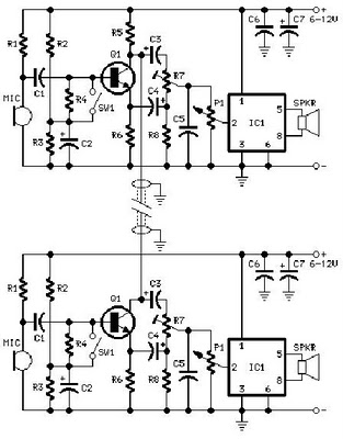
2 phone Intercom circuit diagram which can be used upto 1km in outdoor using ringer
A project is proposed to construct a two-phone intercom system capable of functioning over a distance of up to 1 kilometer. The system will utilize the speaker of each phone to produce a ringing sound on the other end.
The design...

Autopatch telephone line interface
This circuit facilitates the communication link between the receiver and the phone line, as well as the phone line and the transmitter, utilizing an operational amplifier (op-amp) for signal amplification.
The described circuit connects a receiver to a phone line and...