


Darkroom timer
#darkroom timer
#LED display
#digit driver
#keyboard
#output switching
#time base
#50/60 Hz
#DPDT switch
#common-cathode

Description: The darkroom timer/controller utilizes a minimal number of external components, including a display, a digit driver, a keyboard, and output switching devices. A 4-digit common-cathode LED display is preferred for use in darkroom settings. The time base is generated by shaping the 50/60 Hz AC line. A double-pole double-throw (DPDT) switch is employed to select a resolution of either 0.1 or 1 second while also adjusting the position of the decimal point. The timer/controller features two switched AC outlets, one designated for the enlarger and the other for the safe light. These outlets operate in a complementary manner, whereby the safe light is illuminated when the enlarger is inactive and turns off during the printing process. The buzzer is of the self-contained oscillator type and functions with DC drive.
The darkroom timer/controller circuit is designed to facilitate precise control over photographic printing processes. The heart of the system is the 4-digit common-cathode LED display, which provides clear visibility of the timing settings in low-light environments. The digit driver interfaces with the display to convert digital signals into a format suitable for driving the LEDs, ensuring accurate representation of the countdown or elapsed time.
The time base is derived from the 50/60 Hz AC line frequency, which is shaped using a rectifier and a timer IC, such as the 555 timer, configured in monostable mode. This approach ensures a stable and reliable timing reference. The DPDT switch allows the user to select between two timing resolutions: 0.1 seconds for fine-tuning and 1 second for standard timing operations. This switch not only alters the timing intervals but also adjusts the decimal point's position on the display, providing intuitive feedback to the user.
The two AC outlets are strategically designed to control the enlarger and the safe light. The enlarger outlet is activated during the printing process, while the safe light outlet remains energized when the enlarger is off. This feature prevents accidental exposure of light-sensitive materials. The switching mechanism can be implemented using relays or solid-state devices, ensuring reliable operation under varying loads.
The buzzer, functioning as an alert mechanism, is integrated into the circuit to signal the completion of the timing cycle. Utilizing a self-contained oscillator design, the buzzer operates on a DC drive, offering a straightforward implementation that minimizes component count while ensuring effective auditory feedback.
Overall, this darkroom timer/controller circuit provides essential functionality for photographers, allowing for precise timing control in the darkroom environment while ensuring safety and usability.The darkroom timer/controller uses few external components: a display, a digit driver, keyboard, and output switching devices. A 4-digit common-cathode LED display is desirable for dark room environments. The time base is provided by shaping up the 50/60 Hz ac line. A DPDT switch (Si) is used to select a resolution of or 1 seconds and to simultaneously move the decimal point
Timer/ controller has two switched ac outlets, one for the enlarger and one for the safe light. They are the complements of each other in that the safe light is on when the enlarger is not active and is off when the enlarger is printing. The buzzer is of the self-contained oscillator variety and operates with dc drive.
The darkroom timer/controller circuit is designed to facilitate precise control over photographic printing processes. The heart of the system is the 4-digit common-cathode LED display, which provides clear visibility of the timing settings in low-light environments. The digit driver interfaces with the display to convert digital signals into a format suitable for driving the LEDs, ensuring accurate representation of the countdown or elapsed time.
The time base is derived from the 50/60 Hz AC line frequency, which is shaped using a rectifier and a timer IC, such as the 555 timer, configured in monostable mode. This approach ensures a stable and reliable timing reference. The DPDT switch allows the user to select between two timing resolutions: 0.1 seconds for fine-tuning and 1 second for standard timing operations. This switch not only alters the timing intervals but also adjusts the decimal point's position on the display, providing intuitive feedback to the user.
The two AC outlets are strategically designed to control the enlarger and the safe light. The enlarger outlet is activated during the printing process, while the safe light outlet remains energized when the enlarger is off. This feature prevents accidental exposure of light-sensitive materials. The switching mechanism can be implemented using relays or solid-state devices, ensuring reliable operation under varying loads.
The buzzer, functioning as an alert mechanism, is integrated into the circuit to signal the completion of the timing cycle. Utilizing a self-contained oscillator design, the buzzer operates on a DC drive, offering a straightforward implementation that minimizes component count while ensuring effective auditory feedback.
Overall, this darkroom timer/controller circuit provides essential functionality for photographers, allowing for precise timing control in the darkroom environment while ensuring safety and usability.The darkroom timer/controller uses few external components: a display, a digit driver, keyboard, and output switching devices. A 4-digit common-cathode LED display is desirable for dark room environments. The time base is provided by shaping up the 50/60 Hz ac line. A DPDT switch (Si) is used to select a resolution of or 1 seconds and to simultaneously move the decimal point
Timer/ controller has two switched ac outlets, one for the enlarger and one for the safe light. They are the complements of each other in that the safe light is on when the enlarger is not active and is off when the enlarger is printing. The buzzer is of the self-contained oscillator variety and operates with dc drive.

Simple flower circuit
The circuit includes resistors Rp1 to Rp13, which serve dual purposes: they scale the resistance for the keyboard and function as timing resistors for the oscillator. Capacitor C2 acts as a wide discharge capacitor, while switches S1 to S13 represent...

Common-cathode-led-display
A Teledyne TSC7135 digital voltmeter (DVM) chip is utilized to control a multiplexed 5-digit display. To facilitate common cathode drive, a CD4513BE CMOS integrated circuit (IC) functions as a segment driver, with selection controlled by pins 17-20 of the DVM...
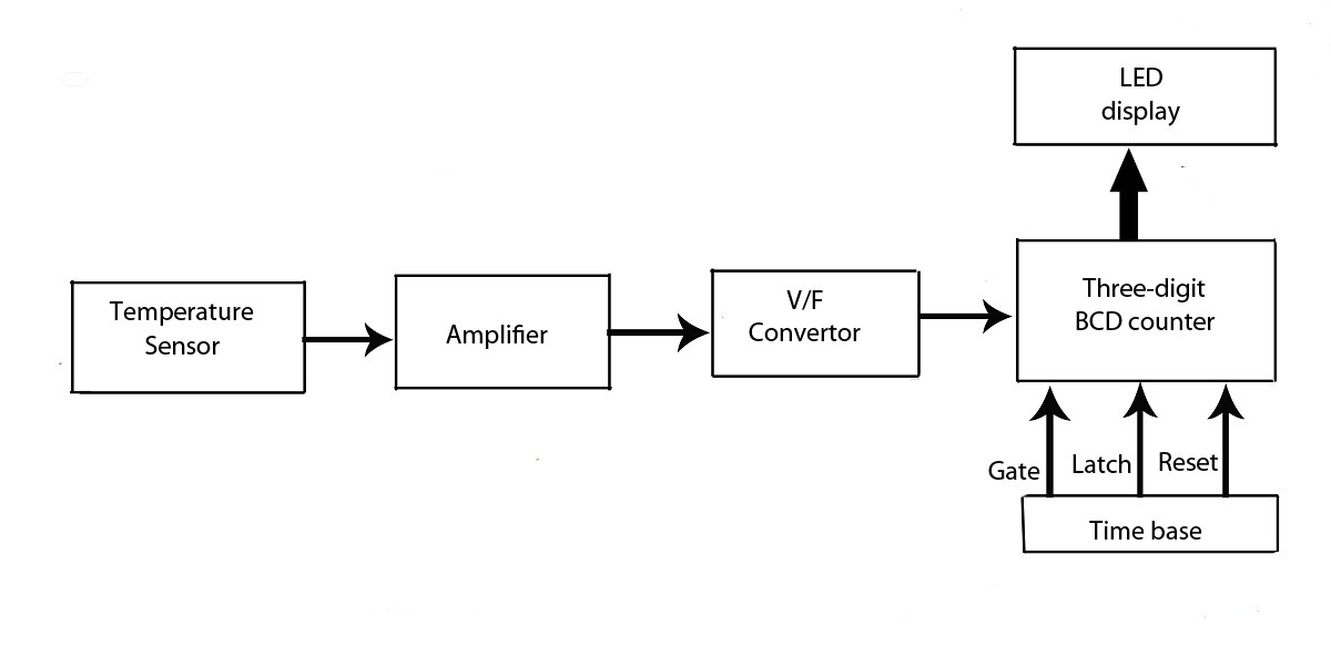
Advanced LED Temperature Indicator
This verified project provides an idea, circuit, and operation of the LED display temperature indicator. It features a digital temperature indicator utilizing a voltage-to-frequency (V/F) converter, along with various electronic projects.
The LED display temperature indicator is designed to provide a...
.gif "Audio Level Meter VU Meter circuit")
Audio Level Meter (VU Meter)
This circuit utilizes a single integrated circuit (IC) along with a minimal number of external components to display audio levels through ten LEDs. The input voltage range is from 12V to 20V, with a recommendation for 12V. The LM3915 is...
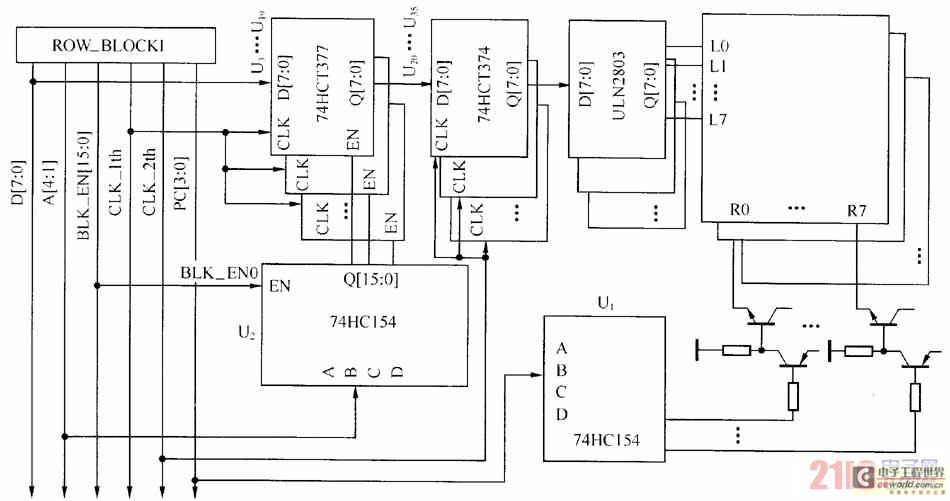
Large-scale LED display system hardware structure and principle
The large-scale LED display system utilizes a line-by-line scanning method and outlines the driving mechanisms to reduce hardware costs. It employs a 1/16 non-interlaced scanning mode, accommodating a total of 16 LED display panels. The schematic diagram of the driver...

8x8 dotmatrix scrolling led display
This project involves a scrolling LED display composed of 64 LEDs arranged in a matrix configuration. The anodes of the LEDs are driven by a driver IC, UDN2981, while the cathodes are controlled using the ULN2803. An Atmega8515 microcontroller is...

Random password keyboard circuit
The design includes a front panel featuring buttons for setting 10 number keys (0-9), along with additional keys such as "Move Down," "Health," "Enter," "Recover," and a "Door Key," totaling 16 keys. The system also incorporates an interior door key...

Spectrum Keyboard Buffer
Most individuals seeking to modify and enhance their Spectrum often focus on the keyboard as a primary area for improvement. However, a straightforward replacement requires opening the computer, which can be discouraging for two main reasons. Firstly, this action may...

interfacing keyboard
A keyboard is a fundamental component of an embedded or microcontroller system. For small-scale and hobby projects, a 4x4 (hex) matrix keyboard is adequate. The keys in the matrix keyboard are arranged in a matrix configuration to efficiently utilize the...