


Delay circuit diagram CC4017 counter divider consisting

Description: CC4017 counter/distributor featuring a circuit diagram of the delay.
The CC4017 is a decade counter and distributor that counts from 0 to 10, providing ten output states. It is commonly used in various digital applications for counting purposes, such as in timers, clocks, and event counters. The device operates on the principle of binary counting, where each output represents a specific count state.
The circuit diagram typically includes the CC4017 IC, which has ten output pins (Q0 to Q9) and a clock input. The clock input triggers the counting sequence, while the reset pin allows the counter to return to zero. The delay aspect of the circuit can be implemented using additional components such as resistors and capacitors, which form an RC timing circuit. This timing circuit can introduce a delay in the clock signal, allowing for controlled counting intervals.
In practical applications, the outputs of the CC4017 can be connected to LEDs to visually indicate the count or to other digital circuits for further processing. The use of the reset feature allows for the counter to be restarted at any time, making it versatile for various timing and counting applications. The design of the circuit must ensure that the power supply voltage is within the specified range for the CC4017 to function correctly, typically between 3V and 15V. Proper bypass capacitors should also be included to stabilize the power supply and prevent noise from affecting the performance of the counter. CC4017 count/distributor consisting of a circuit diagram of the delay:
The CC4017 is a decade counter and distributor that counts from 0 to 10, providing ten output states. It is commonly used in various digital applications for counting purposes, such as in timers, clocks, and event counters. The device operates on the principle of binary counting, where each output represents a specific count state.
The circuit diagram typically includes the CC4017 IC, which has ten output pins (Q0 to Q9) and a clock input. The clock input triggers the counting sequence, while the reset pin allows the counter to return to zero. The delay aspect of the circuit can be implemented using additional components such as resistors and capacitors, which form an RC timing circuit. This timing circuit can introduce a delay in the clock signal, allowing for controlled counting intervals.
In practical applications, the outputs of the CC4017 can be connected to LEDs to visually indicate the count or to other digital circuits for further processing. The use of the reset feature allows for the counter to be restarted at any time, making it versatile for various timing and counting applications. The design of the circuit must ensure that the power supply voltage is within the specified range for the CC4017 to function correctly, typically between 3V and 15V. Proper bypass capacitors should also be included to stabilize the power supply and prevent noise from affecting the performance of the counter. CC4017 count/distributor consisting of a circuit diagram of the delay:
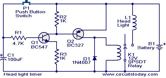
Head light timer circuit
This circuit is a compact timer designed to keep the headlights of a car illuminated for approximately 1.5 minutes before automatically turning them off. By integrating this circuit into a vehicle, users can access dark areas without the need to...

Delay On Circuit
Protect your LCD or Plasma TV with this small delay-on circuit. The SMPS-based power supply of these modern electronic devices is susceptible to voltage spikes.
This delay-on circuit is designed to enhance the protection of LCD and Plasma TVs by mitigating...

4013 datasheet
The 4013 dual D-type flip-flop is a monolithic complementary MOS (CMOS) integrated circuit constructed with N-channel and P-channel enhancement mode transistors. Each flip-flop has a data input (D), a clock input (CLK), a set input (SET), a reset input (RESET),...
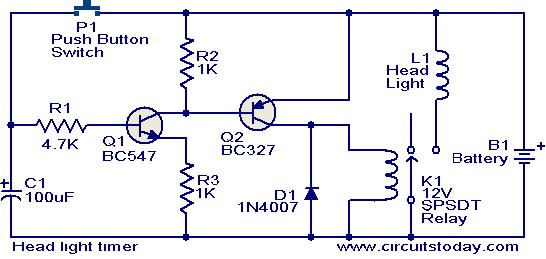
Head light timer circuit
This circuit is a compact timer that keeps the headlights of a car on for approximately 1.5 minutes before turning them off. Incorporating this circuit into a vehicle allows access to dark areas without the need to return and manually...

Delay circuit for a long time periods ( 4060 )
If you need a timer circuit, we go after the most proven 555. However, if the delays are longer, based on timing capacitor capacity is too large. In this case, a circuit of Figure 1 After pressing the button -...

repeating timer no4
This circuit functions as the inverse of Repeating Timer No. 3. Its operation is constrained to the hours of darkness. The variable resistor (preset) allows for the selection of the darkness level at which the timer will activate.
The circuit is...

Cmos line receiver
The trip point is set halfway between the supplies by R1 and R2; R3 provides over 200 mV of hysteresis to increase noise immunity. The maximum frequency of operation is about 300 kHz. If response to TTL levels is desired,...

MULTIDIGIT DEMONSTRATION COUNTER
A simple interconnection of the RS7490 decade counter, RS7447 decoder, and a 7-segment digital display for each desired digit creates an ideal counter for classroom demonstrations and science fair exhibits. With the addition of two extra stages, the display can...

Conducting pipe control one rechargeable short delay circuit
The delay time ranges from 0.5 to 3.5 seconds, which can be adjusted using the potentiometer RP to modify the delay duration.
The circuit utilizes a timing mechanism that allows for the adjustment of delay intervals between 0.5 seconds and 3.5...