


Delay Switch
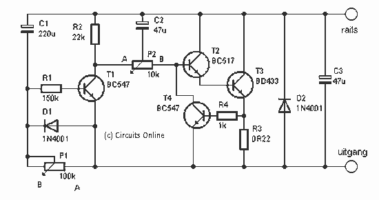
Description: This switch allows the model train at such a station to automatically slow down. The train stands for a certain amount of time and then slowly pulls back. You do not need to stop the train. The relatively simple circuit works. P1 potentiometer for setting the waiting time, while turning to A causes a shorter waiting time and turning to B results in a longer waiting period. P2 is to set the brake and acceleration. Here, too, turning to A results in faster acceleration and the train slows.
The connections of the switch are also simple. The indicated connections on the track with the switch connected. In the broken piece of the train, it will slow down and wait. At H0, this piece is about 1 meter, and at 0.5 N m. Of course, this also depends on the length of the train. When the circuit is connected as shown, the train will stop in one direction only. To allow the train to stop in both directions, a bridge rectifier should be mounted between the rail terminals and the circuit with the AC terminals on the rails, plus the 'rails' terminal and ground to the 'output' connection. A switch can also be installed on the two terminals of the switch. When the switch is closed, the train stops and does not just drive by. A final transistor T3 requires a small heat sink to be mounted. The switch can then handle a current of up to 2 A.
R1 = 150 kOhm
R2 = 22 kOhm
R3 = 0.22 Ω / 2 W
R4 = 1 kOhm
P1 = 100 kOhm
P2 = 10 kΩ
C1 = 220 V µF/16
C2, C3 = 47 µF/16 V
T1, D2 = 1N4002
T1, T4 = 547 BC
T2 = 517 BC
T3 = BD 433
The described circuit functions as a control mechanism for model trains, particularly at stations where a stop-and-go operation is desired. The use of two potentiometers (P1 and P2) allows for user-defined adjustments of waiting time and acceleration rates, enhancing the flexibility of the system. P1 adjusts the duration the train remains stationary, with the ability to fine-tune this based on operational requirements. P2 governs the rate of acceleration and deceleration, allowing for a more realistic train operation.
The circuit utilizes a combination of resistors (R1, R2, R3, R4) to set appropriate biasing levels and current limits for the transistors (T1, T2, T3, T4), which act as switches to control the flow of current to the train's motor. The inclusion of capacitors (C1, C2, C3) serves to filter voltage spikes and stabilize the power supply, ensuring smooth operation of the circuit.
In terms of connectivity, the circuit is designed to be straightforward, allowing for easy integration with existing model train setups. The suggestion to use a bridge rectifier for bi-directional operation indicates a level of sophistication in the design, accommodating trains that may need to reverse direction without requiring manual intervention.
The specifications for the components suggest a robust design capable of handling the electrical demands of model train operation, particularly with the transistor T3 rated for a current of up to 2 A, making it suitable for most model train motors. The heat sink requirement for T3 further indicates that the circuit is designed to dissipate heat effectively, ensuring reliability during extended use.
Overall, this circuit provides a practical solution for automating model train operations at stations, enhancing user experience through adjustable parameters and reliable performance.This switch allows the model train at such a station will automatically slow down. The train stands for a certain amount of time and then slowly pulls back. You do not own the train to stop. The relatively simple circuit works. P1 potentiometer for setting the waiting time, while turning to A caused a shorter waiting time and turn to B results in a longer waiting period. P2 is to set the brake and acceleratieweg. Here, too, turn to A results in faster acceleration and the train slows. The connections of the switch are also simple (see picture connections). The indicated connections on track with the switch connected. In the broken piece of the train will slow down and wait. At H0, this piece is about 1 meter to be, and at 0.5 N m. Of course this also depends on the length of the train. When the circuit is connected as shown, the train will stop in one direction only. Want to train in both directions to stop, then mount a bridge rectifier between the rail terminals and the circuit with the AC terminals on the rails, plus the 'rails' terminal and ground to the' uitgang' connection. You can also stop off. Install a switch on the two terminals of the switch. When the switch is closed, the train stops and not just drive by. Final Transistor T3 is a small heat sink to be screwed. The switch can then flow up to 2 A. R1 = 150 kOhm R2 = 22 kOhm R3 = 0.22 ? / 2 W R4 = 1 kOhm P1 = 100 kOhm P2 = 10kW C1 = 220 V ?F/16 C2, C3 = 47 ?F/16 V T1, D2 = 1N4002 T1, T4 = 547 BC T2 = 517 BC T3 = BD 433
The connections of the switch are also simple. The indicated connections on the track with the switch connected. In the broken piece of the train, it will slow down and wait. At H0, this piece is about 1 meter, and at 0.5 N m. Of course, this also depends on the length of the train. When the circuit is connected as shown, the train will stop in one direction only. To allow the train to stop in both directions, a bridge rectifier should be mounted between the rail terminals and the circuit with the AC terminals on the rails, plus the 'rails' terminal and ground to the 'output' connection. A switch can also be installed on the two terminals of the switch. When the switch is closed, the train stops and does not just drive by. A final transistor T3 requires a small heat sink to be mounted. The switch can then handle a current of up to 2 A.
R1 = 150 kOhm
R2 = 22 kOhm
R3 = 0.22 Ω / 2 W
R4 = 1 kOhm
P1 = 100 kOhm
P2 = 10 kΩ
C1 = 220 V µF/16
C2, C3 = 47 µF/16 V
T1, D2 = 1N4002
T1, T4 = 547 BC
T2 = 517 BC
T3 = BD 433
The described circuit functions as a control mechanism for model trains, particularly at stations where a stop-and-go operation is desired. The use of two potentiometers (P1 and P2) allows for user-defined adjustments of waiting time and acceleration rates, enhancing the flexibility of the system. P1 adjusts the duration the train remains stationary, with the ability to fine-tune this based on operational requirements. P2 governs the rate of acceleration and deceleration, allowing for a more realistic train operation.
The circuit utilizes a combination of resistors (R1, R2, R3, R4) to set appropriate biasing levels and current limits for the transistors (T1, T2, T3, T4), which act as switches to control the flow of current to the train's motor. The inclusion of capacitors (C1, C2, C3) serves to filter voltage spikes and stabilize the power supply, ensuring smooth operation of the circuit.
In terms of connectivity, the circuit is designed to be straightforward, allowing for easy integration with existing model train setups. The suggestion to use a bridge rectifier for bi-directional operation indicates a level of sophistication in the design, accommodating trains that may need to reverse direction without requiring manual intervention.
The specifications for the components suggest a robust design capable of handling the electrical demands of model train operation, particularly with the transistor T3 rated for a current of up to 2 A, making it suitable for most model train motors. The heat sink requirement for T3 further indicates that the circuit is designed to dissipate heat effectively, ensuring reliability during extended use.
Overall, this circuit provides a practical solution for automating model train operations at stations, enhancing user experience through adjustable parameters and reliable performance.This switch allows the model train at such a station will automatically slow down. The train stands for a certain amount of time and then slowly pulls back. You do not own the train to stop. The relatively simple circuit works. P1 potentiometer for setting the waiting time, while turning to A caused a shorter waiting time and turn to B results in a longer waiting period. P2 is to set the brake and acceleratieweg. Here, too, turn to A results in faster acceleration and the train slows. The connections of the switch are also simple (see picture connections). The indicated connections on track with the switch connected. In the broken piece of the train will slow down and wait. At H0, this piece is about 1 meter to be, and at 0.5 N m. Of course this also depends on the length of the train. When the circuit is connected as shown, the train will stop in one direction only. Want to train in both directions to stop, then mount a bridge rectifier between the rail terminals and the circuit with the AC terminals on the rails, plus the 'rails' terminal and ground to the' uitgang' connection. You can also stop off. Install a switch on the two terminals of the switch. When the switch is closed, the train stops and not just drive by. Final Transistor T3 is a small heat sink to be screwed. The switch can then flow up to 2 A. R1 = 150 kOhm R2 = 22 kOhm R3 = 0.22 ? / 2 W R4 = 1 kOhm P1 = 100 kOhm P2 = 10kW C1 = 220 V ?F/16 C2, C3 = 47 ?F/16 V T1, D2 = 1N4002 T1, T4 = 547 BC T2 = 517 BC T3 = BD 433

5 to 30 Minute Timer
A switched timer for intervals of 5 to 30 minutes incremented in 5 minute steps. Simple to build, simple to make, nothing too complicated here. However, you must use the CMOS type 555 timer designated the 7555; a normal 555...

automatic pet feeder
An automatic feeder dispenses food based on the activation of a series of buttons, which interface with a system controller and a food dispenser. The system is designed for intelligent processing of inputs and outputs, allowing dynamic configuration of button...

A Light Operated Repeating Timer Circuit
This circuit closely resembles Repeating Timer No. 2. However, the inclusion of a light-dependent resistor (LDR) allows the timer's operation to be confined to daylight hours. Resistor R7 enables the adjustment of the light level at which the timer will...

Timing within the one-chip computer Counter and interrupt system
This document will present an overview of two critical components within a one-chip computer: the timing/counter system and the interrupt system. Through this explanation, readers will gain insight into the operating principles of these systems. For illustration, consider an alarm...
Time Switch
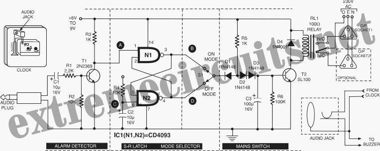
This circuit is specifically designed for individuals who frequently need to wake up early in the morning. Standard alarms in electronic watches are often insufficiently loud.
The circuit utilizes a high-decibel audio output mechanism to ensure that the alarm is audible...
Long duration timer circuit
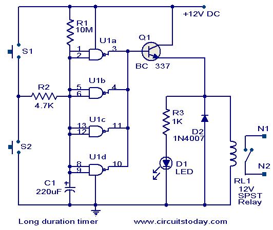
This timer circuit is designed to turn off a specific device after approximately 35 minutes. It can be utilized to switch off appliances such as radios, TVs, fans, and pumps after a predetermined duration of 35 minutes, contributing to significant...

Novel circuit diagram of the timer switch
A novel timing switch circuit features a "Variable Timing" adjustment function in addition to a standard timing circuit. It also includes a countdown display feature, which indicates the remaining time of the timing circuit, making it particularly useful. The entire...

Model Train Diesel and Horn Circuit
The main power supply to the system must be a regulated 12 volts DC with a minimum input from the train control AC or DC power supply of 13.5 VAC connected to pos 3 and 4 of the rectifier bridge....
Tan Timer
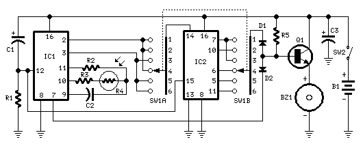
This timer was designed for people wanting to get tanned but at the same time wishing to avoid an excessive exposure to sunlight. A Rotary Switch sets the timer according to six classified Photo-types (see table). A Photo resistor extends...