


Door chimes delay
#door chimes
#delay
#timer
#capacitor
#resistor
#simple circuit
#button
#charging circuit
#time control

Description: With the specified values, this simple circuit will allow one operation approximately every 10 seconds. Capacitor C1 charges through resistor R1 when the button is released. Increasing the resistance of R1 will lengthen the delay.
This circuit functions as a basic timer using a capacitor and resistor in a charging configuration. When the button is pressed, it initiates the operation, and upon release, the capacitor C1 begins to charge through the resistor R1. The time it takes for the capacitor to charge to a certain voltage level determines the delay before the next operation can occur. The time constant of the circuit, which is the product of the resistance (R1) and the capacitance (C1), dictates the charging time.
The relationship between the resistance and the delay is linear; thus, increasing the resistance value of R1 will proportionally increase the time it takes for the capacitor to reach the threshold voltage required to trigger the circuit's next operation. This can be useful in applications where a precise timing interval is necessary, such as in timers, delay circuits, or pulse generators.
In practical applications, selecting the appropriate values for R1 and C1 is crucial to achieving the desired delay. For instance, if a longer delay is required, a larger resistor or capacitor can be selected. Conversely, for shorter delays, smaller values should be chosen. Additionally, it is important to consider the voltage rating of the capacitor to ensure it can handle the charged voltage without failure.
Proper circuit layout and component selection will ensure reliable operation and longevity of the circuit. The simplicity of this design makes it an excellent choice for educational purposes, as well as for use in basic electronic projects where timing control is needed.With values shown, this simple circuit will permit one operation every 10 seconds or so. Capacitor C1 charges through Rl when the button is released Making Rl larger will increase the delay.
This circuit functions as a basic timer using a capacitor and resistor in a charging configuration. When the button is pressed, it initiates the operation, and upon release, the capacitor C1 begins to charge through the resistor R1. The time it takes for the capacitor to charge to a certain voltage level determines the delay before the next operation can occur. The time constant of the circuit, which is the product of the resistance (R1) and the capacitance (C1), dictates the charging time.
The relationship between the resistance and the delay is linear; thus, increasing the resistance value of R1 will proportionally increase the time it takes for the capacitor to reach the threshold voltage required to trigger the circuit's next operation. This can be useful in applications where a precise timing interval is necessary, such as in timers, delay circuits, or pulse generators.
In practical applications, selecting the appropriate values for R1 and C1 is crucial to achieving the desired delay. For instance, if a longer delay is required, a larger resistor or capacitor can be selected. Conversely, for shorter delays, smaller values should be chosen. Additionally, it is important to consider the voltage rating of the capacitor to ensure it can handle the charged voltage without failure.
Proper circuit layout and component selection will ensure reliable operation and longevity of the circuit. The simplicity of this design makes it an excellent choice for educational purposes, as well as for use in basic electronic projects where timing control is needed.With values shown, this simple circuit will permit one operation every 10 seconds or so. Capacitor C1 charges through Rl when the button is released Making Rl larger will increase the delay.

Capacitor step-down DC power supply circuit
A capacitor step-down DC power supply circuit is presented. This circuit eliminates the need for power transformers, utilizing capacitive voltage drop rectification and regulation, which significantly reduces the overall size of the circuit. The circuit includes a capacitor step-down component,...

A bedside lamp delay circuit
The circuit includes a CD4 component with a connection of 16 feet for the Vcc terminal, 8 feet for the ground, 12 feet for the reset terminal, 7 feet for the Qt end, and 3 feet for the Q end....

Precision time-countdown timer
The circuit employs an ICM7213 precision timebase generator with a frequency of 4.1943 MHz, which is utilized for generating pulses that are counted by an ICM7217B counter. Thumbwheel switches are incorporated to allow the user to input a starting time...

simple delay speaker circuit schematic
This circuit was designed for an audio amplifier project to control the speaker output relay. The primary function of this circuit is to manage the relay that activates the speaker output in the audio amplifier. The circuit introduces a delay...

adj pwr
The design incorporates a universal capacitor mounting and spacing feature, enabling compatibility with various capacitor types. It includes a mounting pattern suitable for TO-200 or TO-218/247 packages, specifically for the pass transistor and the transistor utilized in the current limit...

Starting Capacitors
Instructions for electric motor start-run capacitors include the use of starting capacitors for air conditioner compressor motors and other electric motors like pumps. This involves diagnostic checks for start or run capacitors, including how to use a volt-ohm meter (VOM)...

Bedside Lamp Timers
The objective of this circuit is to power a lamp or other device for a predetermined duration (30 minutes in this instance) and subsequently turn it off. This functionality is particularly beneficial for reading in bed at night, as it...
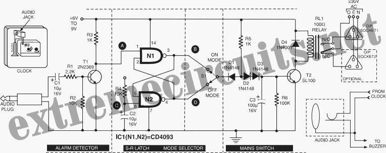
Time Switch
This circuit is specifically designed for individuals who frequently need to wake up early in the morning. Standard alarms in electronic watches are often insufficiently loud.
The circuit utilizes a high-decibel audio output mechanism to ensure that the alarm is audible...

Help me Understand this Circuit Schematic
The roles of capacitors C1, C4, and C5 in a circuit may not be immediately clear. Capacitors on the power rail help to smooth out the signal by reducing current ripple, which can be observed using an oscilloscope. Resistors R6...