


Light timer switch with PIC12F629
#PIC12F629
#timer
#relay
#delay
#light control
#microcontroller
#LED indicator
#customizable
#button control

Description: This is a lamp timer capable of operating two separate relay switches. Outputs can be in three (or restricted to two) states: OFF, delayed ON and constant ON. Delayed ON mode is indicated by the LEDs. The source code is easily customizable for your needs: set your desired delay time or disable constant ON state. press the button once to turn on the lamp for a pre-defined delay. while ON, press the button again to turn the lamp constant ON (turn off delay timer). press the button again to turn the lamp OFF. alternative operation, if you disable the constant ON mode: press the button once to turn on the lamp for a pre-defined delay. while ON, press the button again to turn the lamp OFF. The source code is freely downloadable. This is written for the PIC12F629, but you can easily adapt it to other controllers like the 16F628 or OTP 12C508. The problem is that 30 minutes don't fit into 16 bits. The simplest solution is to increase MHZ to 12, so for the default dly_a, dly_b values you get 9 and 30 mins (the values specified get measured in 30ms instead of 10ms).
The lamp timer circuit is designed to control two relay switches, allowing for versatile operation modes: OFF, delayed ON, and constant ON. It utilizes a microcontroller, specifically the PIC12F629, although it can be adapted for use with other microcontrollers such as the PIC16F628 or OTP 12C508. The microcontroller interfaces with the relay switches to control the lamp based on user input.
The operation of the timer is facilitated through a single push-button interface. The user can initiate the lamp operation by pressing the button once, which activates the lamp for a pre-defined delay period. During this period, pressing the button again will switch the lamp to a constant ON state, effectively disabling the delay timer. A subsequent press of the button will turn the lamp OFF.
If the constant ON mode is disabled, the operation changes slightly: pressing the button once will again turn on the lamp for the specified delay. However, pressing the button a second time will turn the lamp OFF instead of switching it to constant ON.
The source code for this application is available for download and is designed to be easily customizable. Users can modify the delay times to suit their specific requirements. Notably, the timing mechanism is constrained by the limitations of the microcontroller's bit addressing; 30 minutes cannot be represented within a 16-bit integer. To overcome this limitation, the clock frequency can be increased to 12 MHz, allowing for the default delay values (dly_a and dly_b) to be set to 9 and 30 minutes, respectively. The timing is measured in 30 ms increments instead of the standard 10 ms, providing a more accurate representation of longer delay periods.
This circuit is suitable for applications where timed control of lighting is necessary, providing users with flexibility in operation while maintaining simplicity in design.This is a lamp timer capable of operating two separate relay switches. Outputs can be in three (or restricted to two) states: OFF, delayed ON and constant ON. Delayed ON mode is indicated by the LEDs. The source code is easily customizable for your needs: set your desired delay time or disable constant ON state. press the button once to turn on the lamp for a pre-defined delay. while ON, press the button again to turn the lamp constant ON (turn off delay timer). press the button again to turn the lamp OFF. alternative operation, if you disable the constant ON mode: press the button once to turn on the lamp for a pre-defined delay.
while ON, press the button again to turn the lamp OFF. The source code is freely downloadable. This is written for the PIC12F629, but you can easily adapt it to other controllers like the 16F628 or OTP 12C508. The problem is that 30 minutes don't fit into 16 bits. The simplest solution is to increase MHZ to 12, so for the default dly_a, dly_b values you get 9 and 30 mins (the values specified get measured in 30ms instead of 10ms).
The lamp timer circuit is designed to control two relay switches, allowing for versatile operation modes: OFF, delayed ON, and constant ON. It utilizes a microcontroller, specifically the PIC12F629, although it can be adapted for use with other microcontrollers such as the PIC16F628 or OTP 12C508. The microcontroller interfaces with the relay switches to control the lamp based on user input.
The operation of the timer is facilitated through a single push-button interface. The user can initiate the lamp operation by pressing the button once, which activates the lamp for a pre-defined delay period. During this period, pressing the button again will switch the lamp to a constant ON state, effectively disabling the delay timer. A subsequent press of the button will turn the lamp OFF.
If the constant ON mode is disabled, the operation changes slightly: pressing the button once will again turn on the lamp for the specified delay. However, pressing the button a second time will turn the lamp OFF instead of switching it to constant ON.
The source code for this application is available for download and is designed to be easily customizable. Users can modify the delay times to suit their specific requirements. Notably, the timing mechanism is constrained by the limitations of the microcontroller's bit addressing; 30 minutes cannot be represented within a 16-bit integer. To overcome this limitation, the clock frequency can be increased to 12 MHz, allowing for the default delay values (dly_a and dly_b) to be set to 9 and 30 minutes, respectively. The timing is measured in 30 ms increments instead of the standard 10 ms, providing a more accurate representation of longer delay periods.
This circuit is suitable for applications where timed control of lighting is necessary, providing users with flexibility in operation while maintaining simplicity in design.This is a lamp timer capable of operating two separate relay switches. Outputs can be in three (or restricted to two) states: OFF, delayed ON and constant ON. Delayed ON mode is indicated by the LEDs. The source code is easily customizable for your needs: set your desired delay time or disable constant ON state. press the button once to turn on the lamp for a pre-defined delay. while ON, press the button again to turn the lamp constant ON (turn off delay timer). press the button again to turn the lamp OFF. alternative operation, if you disable the constant ON mode: press the button once to turn on the lamp for a pre-defined delay.
while ON, press the button again to turn the lamp OFF. The source code is freely downloadable. This is written for the PIC12F629, but you can easily adapt it to other controllers like the 16F628 or OTP 12C508. The problem is that 30 minutes don't fit into 16 bits. The simplest solution is to increase MHZ to 12, so for the default dly_a, dly_b values you get 9 and 30 mins (the values specified get measured in 30ms instead of 10ms).

Adjustable 1-10 Minute Timer Project
The circuit begins timing upon activation. A green LED illuminates to indicate that timing is in progress. Once the designated time period elapses, the green LED turns off, the red LED activates, and a bleeper emits sound. The duration is...

Headlights Timer
This device is a simple timer that allows the headlights of a vehicle to remain on for approximately 1 minute and 30 seconds. This feature is useful when accessing dark areas without the need to return to turn off the...
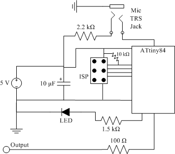
clap sensor construction
The clap sensor is a straightforward circuit that consists of a PC microphone, a microcontroller, and an output. The circuit design features the ATtiny84 microcontroller, chosen for familiarity with the AVR architecture and accessibility to necessary tools. The ATtiny84 is...

Robot Motor Control Schematic
The schematic for controlling the motors is divided into three main sections, each serving a distinct function. The primary components featured in the schematic include the PIC 18F252 microcontroller, the SN754410 motor driver, and 2N2222 transistors. At the top of...
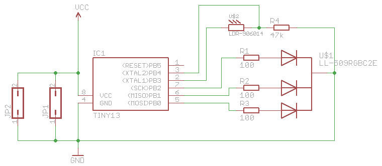
synchronizing fireflies ng
This is a remake of the fireflies project that was created a year ago. The concept revolves around the emergence of patterns, particularly the synchronization of hundreds or thousands of fireflies. Initially, they flash randomly, but over time, influenced by...

Flashflex Microcontroller Control Of Character Lcd Module
The FM497 is an integrated electronic ignition controller designed for breakerless ignition systems that utilize Hall effect sensors. This device operates an external NPN Darlington transistor to manage the coil current, thereby delivering the necessary stored energy while maintaining low...

zener Flyback diodes issues and pull-in & hold current issues in this Relay circuit
Although this may be a basic question, there is still some struggle with it. In this schematic, two zener diodes D1 and D2 are connected back-to-back across relay coil L1. The breakdown voltage (BVds) is -30V for Q1. The question...

Airplane Flight Timer
The following circuit illustrates an Airplane Flight Timer Circuit Diagram. Features include switches in the closed position and battery voltage maintained at a safe level.
The Airplane Flight Timer Circuit is designed to provide a reliable timing mechanism for monitoring flight...

Model rocket launcher
The circuit comprises a launch timer and an automatic-off timer. Upon applying power to the integrated circuit (IC), the countdown LED sequence activates until all LEDs are illuminated. When the last LED (LED1) is fully lit, transistor Q1 enters saturation,...