


onoff 24 hours timer circuit schematic

Description: The CMOS 4060 is a 14-bit binary counter; however, only ten of these bits are connected to output pins. The 4060 also includes two inverters, which are connected in series across pins 11, 10, and 9. Together with resistors R3, R4, R5, and capacitor C3, they create a simple oscillator. While the oscillator operates, the 14-bit counter counts the number of oscillations, and the state of the count is reflected on the output pins. By adjusting R4, the frequency of the oscillator can be altered, allowing control over the count progression speed. This means the duration for which any given output pin remains high can be determined. When an output pin goes high, it activates a transistor, which in turn operates a relay. In single-shot mode, the output pin has an additional function; it uses diode D1 to disable the oscillator, causing the count to stop when the output pin is high. To utilize the timer in repeating mode, D1 should be omitted, allowing the count to continue indefinitely, with the output pin cyclically switching the transistor on and off at regular intervals.
The CMOS 4060 is a versatile integrated circuit that combines a binary counter and an oscillator, making it suitable for various timing applications. The counter operates by counting the oscillations generated by the oscillator circuit. The oscillator is formed by the two inverters and the passive components R3, R4, R5, and C3, which determine the frequency of oscillation. The output frequency can be finely tuned through R4, allowing for precise timing control.
The ten output pins of the counter can be utilized to indicate the current count, enabling the design of digital clocks, timers, and frequency dividers. The ability to switch the transistor via the output pins allows for the control of larger loads, such as relays, which can be used to switch on or off various devices in response to the counter's state.
In single-shot mode, the configuration with diode D1 prevents further oscillations once the desired count is reached, making it ideal for applications requiring a one-time event trigger. Conversely, by excluding D1, the circuit can operate in a continuous mode, providing a repetitive output signal that can be used for applications such as pulse-width modulation or regular timing signals.
The CMOS 4060's flexibility and ease of use make it a valuable component in electronic designs, allowing engineers to create efficient and reliable timing solutions in a compact form factor.The Cmos 4060 is a 14-bit binary counter. However - only ten of those bits are connected to output pins. The 4060 also has two inverters - connected in series across pins 11, 10 & 9. Together with R3, R4, R5 and C3 - they form a simple oscillator. While the oscillator is running - the 14-bit counter counts the number of oscillations - and the stat e of the count is reflected in the output pins. By adjusting R4 you can alter the frequency of the oscillator. So you can control the speed at which the count progresses. In other words - you can decide how long it will take for any given output pin to go high. When that pin goes high - it switches the transistor - and the transistor in turn operates the relay. In single-shot mode - the output pin does a second job. It uses D1 to disable the oscillator - so the count stops with the output pin high. If you want to use the timer in repeating mode - simply leave out D1. The count will carry on indefinitely. And the output pin will continue to switch the transistor on and off - at the same regular time intervals.
The CMOS 4060 is a versatile integrated circuit that combines a binary counter and an oscillator, making it suitable for various timing applications. The counter operates by counting the oscillations generated by the oscillator circuit. The oscillator is formed by the two inverters and the passive components R3, R4, R5, and C3, which determine the frequency of oscillation. The output frequency can be finely tuned through R4, allowing for precise timing control.
The ten output pins of the counter can be utilized to indicate the current count, enabling the design of digital clocks, timers, and frequency dividers. The ability to switch the transistor via the output pins allows for the control of larger loads, such as relays, which can be used to switch on or off various devices in response to the counter's state.
In single-shot mode, the configuration with diode D1 prevents further oscillations once the desired count is reached, making it ideal for applications requiring a one-time event trigger. Conversely, by excluding D1, the circuit can operate in a continuous mode, providing a repetitive output signal that can be used for applications such as pulse-width modulation or regular timing signals.
The CMOS 4060's flexibility and ease of use make it a valuable component in electronic designs, allowing engineers to create efficient and reliable timing solutions in a compact form factor.The Cmos 4060 is a 14-bit binary counter. However - only ten of those bits are connected to output pins. The 4060 also has two inverters - connected in series across pins 11, 10 & 9. Together with R3, R4, R5 and C3 - they form a simple oscillator. While the oscillator is running - the 14-bit counter counts the number of oscillations - and the stat e of the count is reflected in the output pins. By adjusting R4 you can alter the frequency of the oscillator. So you can control the speed at which the count progresses. In other words - you can decide how long it will take for any given output pin to go high. When that pin goes high - it switches the transistor - and the transistor in turn operates the relay. In single-shot mode - the output pin does a second job. It uses D1 to disable the oscillator - so the count stops with the output pin high. If you want to use the timer in repeating mode - simply leave out D1. The count will carry on indefinitely. And the output pin will continue to switch the transistor on and off - at the same regular time intervals.

Oscillator-clock generator
This self-starting fixed frequency oscillator circuit provides excellent frequency stability. R1 and C1 form the frequency-determining network, while R2 supplies regenerative feedback. Diode D1 improves stability by compensating for the difference between Voh and Vsupply. In applications requiring a precision...

Safety flare
When the switch SI is activated, power is supplied to an oscillator that consists of Q1, R1, C1, L1, and L2. Coil L1 serves as the primary winding of transformer T1, while L2 functions as the feedback winding. As Q1...

automatic dual output display circuit diagram
This circuit lights up ten bulbs sequentially, first in one direction and then in the opposite direction, creating an appealing visual effect. In this circuit, gates N1 and N2 form an oscillator. The output of this oscillator serves as a...

150 To 30000Khz Oscillator
A capacitor in series with the crystal can be utilized to adjust the output frequency of the oscillator. The value can range between 20 pF and 0.01 µF, or it can be a trimmer capacitor. The values are approximate and...
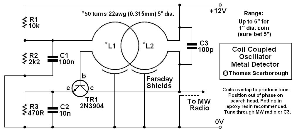
coil coupled operation metal
The metal detector presented may represent a new category in its field. After some exposure, it has been recognized as such by those familiar with it. This device is based on a standard transformer coupled oscillator (TCO), which is why...

Metallic pipe detector
This circuit employs a 15-kHz oscillator coil. When metal is removed from the energy field, the oscillator voltage is rectified and compared to a reference. A decrease in oscillator voltage activates comparator IC2, causing D4 (LED) to turn off.
L1 consists...

Very Simple Oscillator
This is the first oscillator that was built. Various resources such as books, magazines, and online schematics were reviewed. Most of the designs encountered were either Colpitts or Hartley oscillators. While these designs are relatively straightforward, they require specific inductors,...

Automatic Dual Output Display
This circuit sequentially lights ten bulbs, first in one direction and then in the opposite direction, creating an appealing visual effect. Gates N1 and N2 form an oscillator, which serves as a clock for the BCD up/down counter CD4510 (IC2)....

simple electronic organ
This electronic organ is simple to construct and can provide hours of enjoyment, particularly for children. The circuit is fundamentally an emitter-coupled oscillator consisting of transistors T2 and T3. A square wave voltage can be sampled from the collector of...