


Power-On Time Delay Relay With LM339 IC
#LM339
#time delay
#relay
#pulse transformer
#thermostat
#heater control
#circuit design
#electronics
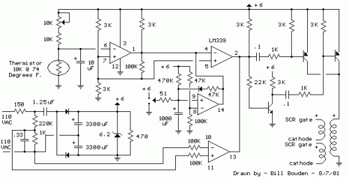
Description: The thermostat circuit is designed to control a 1300-watt space heater using a small pulse transformer. Component: LM339 IC.
The thermostat circuit utilizes an LM339 integrated circuit (IC) to manage the operation of a 1300-watt space heater. The LM339 is a quad comparator that can compare voltage levels and provide output signals based on these comparisons. In this application, the circuit is configured to monitor the temperature of the environment and activate or deactivate the heater accordingly.
The circuit typically includes temperature sensors, such as thermistors or thermocouples, which provide a voltage output proportional to the temperature. These sensors are connected to the inputs of the LM339. The reference voltage for the comparators can be set using a voltage divider or a potentiometer, allowing for calibration of the desired temperature threshold.
When the temperature falls below the set point, the output from the LM339 changes state, triggering a control mechanism, often through a relay or a solid-state switch, to turn on the heater. Conversely, when the temperature exceeds the set threshold, the LM339 output will deactivate the heater, ensuring that the space remains within the desired temperature range.
The use of a small pulse transformer in the circuit provides electrical isolation between the control circuit and the high-power heater, enhancing safety and preventing damage to the control components. Additionally, the transformer can help to reduce electromagnetic interference, ensuring stable operation of the thermostat.
Overall, this thermostat circuit efficiently manages the heating process, optimizing energy consumption while maintaining comfort in the controlled environment.The thermostat circuit built to control a 1300 watt space heater which are controlled with a small pulse transformer. Component: LM339 IC, ..
The thermostat circuit utilizes an LM339 integrated circuit (IC) to manage the operation of a 1300-watt space heater. The LM339 is a quad comparator that can compare voltage levels and provide output signals based on these comparisons. In this application, the circuit is configured to monitor the temperature of the environment and activate or deactivate the heater accordingly.
The circuit typically includes temperature sensors, such as thermistors or thermocouples, which provide a voltage output proportional to the temperature. These sensors are connected to the inputs of the LM339. The reference voltage for the comparators can be set using a voltage divider or a potentiometer, allowing for calibration of the desired temperature threshold.
When the temperature falls below the set point, the output from the LM339 changes state, triggering a control mechanism, often through a relay or a solid-state switch, to turn on the heater. Conversely, when the temperature exceeds the set threshold, the LM339 output will deactivate the heater, ensuring that the space remains within the desired temperature range.
The use of a small pulse transformer in the circuit provides electrical isolation between the control circuit and the high-power heater, enhancing safety and preventing damage to the control components. Additionally, the transformer can help to reduce electromagnetic interference, ensuring stable operation of the thermostat.
Overall, this thermostat circuit efficiently manages the heating process, optimizing energy consumption while maintaining comfort in the controlled environment.The thermostat circuit built to control a 1300 watt space heater which are controlled with a small pulse transformer. Component: LM339 IC, ..

Reducing Relay Power Consumption
Relays are commonly utilized as electrically controlled switches. Unlike transistors, the switch contacts of relays are electrically isolated from the control input. However, the power dissipation in a relay coil can be undesirable for battery-operated applications. The incorporation of an...

Power-Off Time Delay Relay circuit
The two circuits demonstrate the process of opening a relay contact shortly after the ignition or light switch is turned off. The capacitor is charged, and the relay remains closed until the voltage at the diode anode reaches +12 volts.
The...

Tarry light
The push button and potentiometer initiate a time delay that turns a light on and then automatically turns it off again after a predetermined time. The potentiometer can be set for a delay of a few seconds to just under...

Run/Stop Relay Circuit
Safety is a significant concern in many motor-driven applications. This is particularly true in industrial settings where motion begins immediately upon the application of power.
In motor-driven applications, safety mechanisms are essential to prevent accidents and ensure the well-being of operators...

Isolated 24V Relay Controller
This is a common control voltage in industrial and telecommunications equipment, making relays frequently found in surplus equipment. Many relays can operate effectively on both AC and DC, providing a straightforward solution when the control voltage is switched mechanically, such...

motorcycle headlight with single spdt relay
A bike equipped with a 35-watt HS1 bulb is being upgraded to a brighter headlight using an H4 60/65-watt xenon bulb. An expert recommended using relays due to the increased power requirements of the new bulb. Research conducted on relay...

DC relay circuits to delay the release of a second
The circuit depicted in Figure 6-24 includes a relay coil with both ends connected in parallel to either a resistor Rf or an auxiliary diode VD. This configuration is equivalent to providing power after a short circuit, which increases the...

Electronic-time-delay
The time delay, T, in seconds is calculated using the formula: T = 1.1 x C1 x (R1 + R2). The resistances are measured in megohms and the capacitances in microfarads. The combined resistance of R1 and R2 should be...

Four reversing operation of the reverse brake circuit
The circuit depicted in Figure 3-131 utilizes a relay instead of a speed control relay. It is designed to operate effectively in dusty environments and other challenging conditions.
The circuit operates by employing a relay as a primary switching mechanism, which...