


Sequential timing control circuit diagram

Description: The timing control circuit is a sequential circuit that allows for sequential timed control of two switches. The control time can be adjusted from a few seconds to several tens of seconds. If mechanical control is applied for reciprocating movement, it can enable the motor to run forward and reverse according to timing requirements.
The timing control circuit operates as a sequential logic system designed to manage the operation of two switches in a predetermined timed sequence. This circuit typically employs flip-flops or counters to generate the necessary timing intervals, allowing for precise control over the activation and deactivation of the switches. The adjustable timing feature is often realized through the use of variable resistors or capacitors, enabling users to set the desired time delay according to specific application needs.
In scenarios where mechanical control is required for reciprocating motion, the circuit can be configured to alternate the state of the switches, thereby controlling the direction of a motor. This functionality is particularly useful in applications such as automated machinery, where forward and reverse motion is needed for tasks such as material handling or assembly processes.
The circuit design may include additional components such as diodes for protection against back EMF generated by the motor, as well as transistors or relays to handle the current required to drive the motor. The integration of these components ensures reliable operation while safeguarding the circuit from potential damage due to inductive loads.
Overall, this timing control circuit provides a versatile solution for applications requiring timed control of mechanical systems, facilitating both forward and reverse motor operation in a controlled manner. As shown in the timing control circuit is a sequential circuit, the circuit can be carried out sequentially timed control of the two switches, control time can be adjusted from a few seconds to several tens fair share; if mechanical control for reciprocating movement of positive and negative, can be It causes the motor to run forward and reverse timing requirements.
The timing control circuit operates as a sequential logic system designed to manage the operation of two switches in a predetermined timed sequence. This circuit typically employs flip-flops or counters to generate the necessary timing intervals, allowing for precise control over the activation and deactivation of the switches. The adjustable timing feature is often realized through the use of variable resistors or capacitors, enabling users to set the desired time delay according to specific application needs.
In scenarios where mechanical control is required for reciprocating motion, the circuit can be configured to alternate the state of the switches, thereby controlling the direction of a motor. This functionality is particularly useful in applications such as automated machinery, where forward and reverse motion is needed for tasks such as material handling or assembly processes.
The circuit design may include additional components such as diodes for protection against back EMF generated by the motor, as well as transistors or relays to handle the current required to drive the motor. The integration of these components ensures reliable operation while safeguarding the circuit from potential damage due to inductive loads.
Overall, this timing control circuit provides a versatile solution for applications requiring timed control of mechanical systems, facilitating both forward and reverse motor operation in a controlled manner. As shown in the timing control circuit is a sequential circuit, the circuit can be carried out sequentially timed control of the two switches, control time can be adjusted from a few seconds to several tens fair share; if mechanical control for reciprocating movement of positive and negative, can be It causes the motor to run forward and reverse timing requirements.

Discharge before memory circuit
Discharge before memory circuit. Before the memory circuit is activated, a delay reset circuit is required. When the input signal triggers an action, timing begins, and after a specified delay, the circuit reverts to its original state. During this interval,...

Intermittent start and stop cycle control circuit of the four
The circuit illustrated in Figure 3-79 consists of two delay circuits. The RPi adjustment potentiometer and RP2 can be modified to control the duration of the motor operation, allowing for arbitrary adjustments within a specified time frame.
The circuit comprises two...
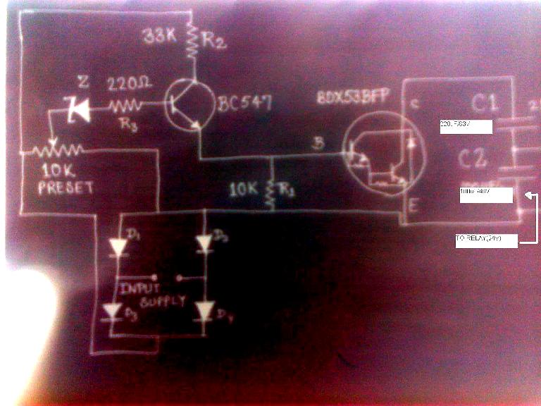
make this simple delay on circuit
The post discusses a simple delay ON circuit that enables a connected load to be powered on with a predetermined delay after the power switch is activated. This circuit is applicable for any scenario that requires an initial delay before...

delay circuit for surround sound
This circuit utilizes the Mitsubishi M65830 Digital Delay chip, which has proven to be simple and effective for applications requiring a fixed delay. The serial data necessary for achieving various delay settings is not readily available and would significantly increase...

The Delay
The delay circuit utilizes the Mitsubishi M65830 Digital Delay chip, as illustrated in Figure 1. This chip has been in use for some time and is known for its simplicity and effectiveness, particularly when a fixed delay is sufficient. However,...
The Delay
The delay circuit utilizes the Mitsubishi M65830 Digital Delay chip, as illustrated in Figure 1. This chip has been in use for some time and is known for its simplicity and effectiveness, particularly when a fixed delay is sufficient. However,...

Digital delay circuit lamp circuit 3
A delay lamp circuit is ideal for bedside tables, featuring a button (SB) that turns the light on and off. If the button is not pressed, the circuit maintains a delay before the light turns off. If the light turns...

Delay circuit for a long time periods ( 4060 )
If you need a timer circuit, we go after the most proven 555. However, if the delays are longer, based on timing capacitor capacity is too large. In this case, a circuit of Figure 1 After pressing the button -...
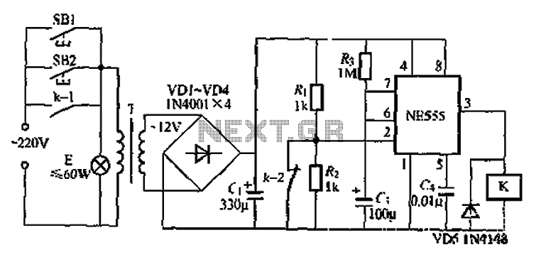
When using the lamp base circuit delay circuit 2
Another application involves the use of a NE555 delay lamp circuit, where components SB1 and SH2 act as J-light buttons that can be installed in two different locations. The lamp can be activated by pressing either SB1 or SB2, which...