


555 timer audio alarm circuits
#555 timer
#audio alarm
#multivibrator
#duty cycle
#loudspeaker
#danger beep
#integrated circuit
#stable oscillator

Description: This is a danger beep circuit. It uses a 555 integrated circuit configured as a stable multivibrator that provides a duty cycle of 5% to drive a loudspeaker.
The danger beep circuit utilizes the 555 timer IC, a versatile and widely used component in electronic circuits for generating precise timing and oscillation. In this configuration, the 555 timer is set up as an astable multivibrator, which means it continuously oscillates between its high and low states, producing a square wave output.
The duty cycle of the circuit is set to 5%, meaning that the output signal remains high for only 5% of the total period and low for the remaining 95%. This low duty cycle is essential for creating a beeping sound that is both short and sharp, ideal for alerting users to potential dangers.
The circuit typically comprises several key components: the 555 timer IC, resistors, capacitors, and a loudspeaker. The resistors determine the charge and discharge times of the timing capacitor, which in turn sets the frequency of the oscillation. By selecting appropriate resistor and capacitor values, the frequency can be adjusted to achieve the desired beep rate.
The output from the 555 timer is connected to a loudspeaker, which converts the electrical signal into audible sound. The speaker's impedance must be matched to the output of the timer to ensure efficient operation. Additionally, a transistor may be included in the circuit to amplify the output signal, allowing for the use of larger speakers or higher volume levels.
Power supply considerations are also important; the 555 timer typically operates within a voltage range of 4.5V to 15V, making it compatible with various battery types or power sources. Proper decoupling capacitors should be placed near the power supply pins of the IC to filter any noise and ensure stable operation.
In summary, the danger beep circuit is an effective application of the 555 timer IC, providing a simple yet reliable means to generate a warning sound through a loudspeaker, making it suitable for various safety and alert systems.This is danger beep circuit. It use 555 integrated number circuits build to are a stable mutivibrator that be valuable duty cycle 5% driver loudspeaker..
The danger beep circuit utilizes the 555 timer IC, a versatile and widely used component in electronic circuits for generating precise timing and oscillation. In this configuration, the 555 timer is set up as an astable multivibrator, which means it continuously oscillates between its high and low states, producing a square wave output.
The duty cycle of the circuit is set to 5%, meaning that the output signal remains high for only 5% of the total period and low for the remaining 95%. This low duty cycle is essential for creating a beeping sound that is both short and sharp, ideal for alerting users to potential dangers.
The circuit typically comprises several key components: the 555 timer IC, resistors, capacitors, and a loudspeaker. The resistors determine the charge and discharge times of the timing capacitor, which in turn sets the frequency of the oscillation. By selecting appropriate resistor and capacitor values, the frequency can be adjusted to achieve the desired beep rate.
The output from the 555 timer is connected to a loudspeaker, which converts the electrical signal into audible sound. The speaker's impedance must be matched to the output of the timer to ensure efficient operation. Additionally, a transistor may be included in the circuit to amplify the output signal, allowing for the use of larger speakers or higher volume levels.
Power supply considerations are also important; the 555 timer typically operates within a voltage range of 4.5V to 15V, making it compatible with various battery types or power sources. Proper decoupling capacitors should be placed near the power supply pins of the IC to filter any noise and ensure stable operation.
In summary, the danger beep circuit is an effective application of the 555 timer IC, providing a simple yet reliable means to generate a warning sound through a loudspeaker, making it suitable for various safety and alert systems.This is danger beep circuit. It use 555 integrated number circuits build to are a stable mutivibrator that be valuable duty cycle 5% driver loudspeaker..

Wide Frequency Range 555 VCO
The frequency of the 555 timer can be adjusted by varying the voltage applied to pin 5. However, the range and linearity of this frequency adjustment are quite limited.
The 555 timer IC is widely used in various applications, including timers,...

Model Train And Slot-Car Controller
A 555 timer (U1) is configured as an astable multivibrator (oscillator) with a duty cycle of 400:1 and a frequency of 40 Hz. When power is applied to the circuit, capacitor C1 (connected to pin 6 of U1) is discharged,...

A bean sprouts automatic watering controller consisting of 555 circuit
The figure illustrates the automatic watering control circuit for bean sprouts. The controller includes a step-down rectifier circuit, a power outage detection component (IC3), a timing control circuit (IC1), and a temperature control circuit (IC2). The step-down rectifier circuit supplies...

555 electronic musical instrument additional combo audio circuit
Adding this combination audio circuit, as illustrated in figure 14-38, to the automatic rhythm generator of electronic musical instruments fulfills the players' demand for incorporating drum and cymbal audio, enhancing the overall performance effect. The diagram indicates that the astable...

Capacitors and the 555 Timer
ECEN 2250 myDAQ Experiment Capacitors and the 555 Timer.
The experiment involving capacitors and the 555 timer within the ECEN 2250 myDAQ framework focuses on understanding the behavior of capacitors in electronic circuits and the functionality of the 555 timer as...
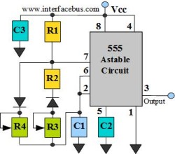
555 Individual Pulse Width circuit
The astable multivibrator circuit lacks a stable state. In the absence of an external signal, the internal transistors alternately switch between cutoff and saturation at a frequency determined by the RC time constants of the coupling circuits. Therefore, an astable...

Timed Burglar Alarm N/O - N/C
This is a simple but effective alarm circuit that can reset itself after a user-defined time. It features normally open and normally closed triggers, enhancing its practicality. The circuit utilizes a 555 timer, allowing the alarm to automatically reset after...

RE POWERED SIDETONE OSCILLATOR
A sidetone oscillator is a specialized audio oscillator that is activated and deactivated in conjunction with the transmitter. This oscillator is driven by RF signals and is powered by batteries. It employs a 555 integrated circuit (IC) timer configured as...

Circuit diagram for generating time delay with 555 IC
This circuit-based project demonstrates the operation of a 555 timer in astable mode to generate pulses with a time period of 0.5 seconds. These pulses can be utilized in various applications, such as blinking an LED or creating decorative blinking...