


A watchdog circuit diagram
#CD4060
#NMOS transistor
#reset pulse
#timing circuit
#watchdog timer
#pulse control
#digital logic
#circuit protection
#safety mechanism
#timing delay

Description: As shown in the figure, the operation of the circuit relies on the timing of the reset pulse to the CD4060. This ensures that the state is finalized in Q1, allowing the NMOS transistor to control the LED, keeping it in the on state and providing power to the processor circuitry. A significant advantage of this circuit is its ability to maintain a relatively long timing duration, lasting several minutes, which is sufficient for system initialization. The pulse triggers the circuit, and when power is applied through R2, C1, and R3, an automatic reset pulse is generated for the counter, ensuring an output Vout. The circuit is cost-effective. However, the primary drawback is that the circuit requires a relatively wide pulse for operation.
The described circuit utilizes a CD4060 integrated circuit, which functions as a frequency divider and oscillator. This device is pivotal in generating the timing signals necessary for the operation of the NMOS transistor and the LED. The reset pulse is essential for initializing the CD4060, ensuring that the output states are correctly set before the circuit begins its primary function.
The timing components, including resistors R2 and R3 and capacitor C1, are configured to create a delay that allows sufficient time for the system to stabilize. The choice of these components directly affects the duration of the reset pulse. A longer time constant can be achieved by increasing the values of R2 and C1, thus providing an extended initialization period for the processor circuitry.
The NMOS transistor serves a dual purpose: controlling the LED and acting as a switch that provides power to the processor. When the reset pulse is active, it ensures that the NMOS transistor remains in the conductive state, allowing current to flow through the LED, which indicates that the circuit is powered and operational.
Despite its advantages, the circuit's reliance on a wide pulse width can limit its applications. The design must ensure that the pulse width is adequate to trigger the NMOS transistor consistently; otherwise, the circuit may fail to operate as intended. Therefore, careful consideration must be given to the pulse generation mechanism to ensure reliable performance.
Overall, this circuit design is an effective solution for applications requiring a delayed initialization sequence, provided that the pulse width requirements are met. Its low cost and simplicity make it a suitable choice for various electronic projects.As Figure: when the operation of the circuit as long as the timing of the reset pulse to the CD4060, we can guarantee the state ended in Q1, so that the NMOS transistor control led in the on state power to the processor circuitry. The advantage of this circuit is that the timing of the time can be relatively long, a few minutes no problem, it can take a long time to those who have enough time to initialize the system for initialization. Pulse trigger the dogs, when the power through R2, C1, R3 an automatic reset pulse to the counter to ensure that there is an output Vout.
Circuit costs low.The biggest drawback of this circuit is that the dogs require a relatively wide pulse.
The described circuit utilizes a CD4060 integrated circuit, which functions as a frequency divider and oscillator. This device is pivotal in generating the timing signals necessary for the operation of the NMOS transistor and the LED. The reset pulse is essential for initializing the CD4060, ensuring that the output states are correctly set before the circuit begins its primary function.
The timing components, including resistors R2 and R3 and capacitor C1, are configured to create a delay that allows sufficient time for the system to stabilize. The choice of these components directly affects the duration of the reset pulse. A longer time constant can be achieved by increasing the values of R2 and C1, thus providing an extended initialization period for the processor circuitry.
The NMOS transistor serves a dual purpose: controlling the LED and acting as a switch that provides power to the processor. When the reset pulse is active, it ensures that the NMOS transistor remains in the conductive state, allowing current to flow through the LED, which indicates that the circuit is powered and operational.
Despite its advantages, the circuit's reliance on a wide pulse width can limit its applications. The design must ensure that the pulse width is adequate to trigger the NMOS transistor consistently; otherwise, the circuit may fail to operate as intended. Therefore, careful consideration must be given to the pulse generation mechanism to ensure reliable performance.
Overall, this circuit design is an effective solution for applications requiring a delayed initialization sequence, provided that the pulse width requirements are met. Its low cost and simplicity make it a suitable choice for various electronic projects.As Figure: when the operation of the circuit as long as the timing of the reset pulse to the CD4060, we can guarantee the state ended in Q1, so that the NMOS transistor control led in the on state power to the processor circuitry. The advantage of this circuit is that the timing of the time can be relatively long, a few minutes no problem, it can take a long time to those who have enough time to initialize the system for initialization. Pulse trigger the dogs, when the power through R2, C1, R3 an automatic reset pulse to the counter to ensure that there is an output Vout.
Circuit costs low.The biggest drawback of this circuit is that the dogs require a relatively wide pulse.

CD4060 production time controller circuit diagram
A CD4060 production time controller circuit is illustrated below. It is connected in such a way that R5 and C3 form a differential circuit to create a delay time from the start. Under the influence of the oscillating signal, the...

1-20 minutes a timing circuit
The system operates between 10 minutes to 2 hours, featuring a 100-line bell controlled by a multi-gear stick labeled S2 41f. The integrated circuit (IC) functions as a self-excited multivibrator. The device can manage binary pulses ranging from 3 to...
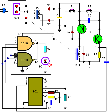
A Bedside Lamp Timer Circuit Schematic With CD4060 IC
The following circuit illustrates the Bedside Lamp Timer Circuit utilizing the CD4060 integrated circuit (IC). It operates for 30 minutes, with a blinking LED indicating the last 6 minutes of operation.
The Bedside Lamp Timer Circuit is designed to provide a...

electronic circuit breaker
A circuit breaker is an automatically operated electrical switch designed to protect an electrical circuit from damage caused by overload or short circuit. Its basic function is to detect a fault condition and, by interrupting continuity, immediately discontinue electrical flow....
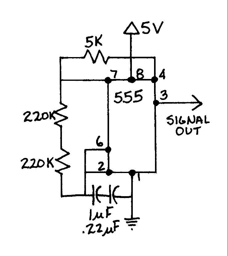
EGR 450 Manufacturing Controls Project
A timing and counting circuit utilizing integrated circuit chips with seven-segment LED displays is employed to show the current lap time, previous lap time, and total number of laps completed on a 1/64th-scale slot car racetrack. A switch activated by...
Bedside Lamp TimerCircuit Based On The CD4060 IC
The following circuit illustrates a Bedside Lamp Timer Circuit Diagram. This circuit is based on the CD4060 integrated circuit. Features: An LED illuminates for approximately 25 seconds.
The Bedside Lamp Timer Circuit utilizes the CD4060 IC, which is a versatile component...

timing circuit
Assistance is needed for the design of a timing circuit intended to activate a spark plug every 10 or 20 revolutions of a shaft.
The timing circuit for firing a spark plug at specified intervals can be designed using a combination...

CD4060 Timer Circuit 1 minute to 2 hours
CD4060 Timer Circuit 1 minute to 2 hours This is a 1 minute to two-hour timer switch. The 14-stage binary ripple counter Type 4060, IC1, has an...
The CD4060 timer circuit is designed to function as a timer switch with a...

Timer with musical alarm
The timer with a musical alarm is an electronic timer project utilizing the CD4060 integrated circuit. It provides a delay ranging from 1 minute to 2 hours. The circuit diagram for the timer with a musical alarm is part of...