


Asymmetric Timer Circuit With 7555 IC
#7555 IC
#astable timer
#resistor
#transistor
#independent mark and space periods
#timer circuit
#pulse generator
#discharge path

Description: The following circuit illustrates a timer circuit with independent mark and space periods. It is based on the 7555 integrated circuit (IC). The high output duration is calculated by T(on) = 0.7 Ra Ct, while the low output duration is determined by T(off) = 0.7 Rb Ct. This circuit operates as an astable timer, allowing (on) and (off) values to be set independently, with a designated discharge path. Components include the 7555 IC, resistors, a transistor, a battery, a switch, a diode, and a capacitor.
The timer circuit utilizing the 7555 IC operates as an astable multivibrator, which continuously switches between its high and low states without requiring any external triggering. The independent mark and space periods allow for flexible timing applications in various electronic projects.
The timing intervals are determined by external resistors (Ra and Rb) and a timing capacitor (Ct). The calculations for the high and low output durations are crucial for achieving the desired frequency of operation. Specifically, T(on) is influenced by the resistance of Ra and the capacitance of Ct, while T(off) is dependent on Rb and Ct. The factor of 0.7 in the formulas accounts for the charging and discharging characteristics of the capacitor in the circuit.
The discharge path is a critical component of the circuit, ensuring that the timing capacitor discharges properly, allowing for consistent timing intervals. The inclusion of a transistor can provide additional control or amplification of the output signal, depending on the circuit's application.
Powering the circuit with a battery ensures portability and ease of use in various settings. A switch is often included to enable or disable the circuit, providing user control over its operation. The diode serves to protect the circuit from reverse polarity, which can occur if the battery is connected incorrectly.
Overall, this timer circuit offers a versatile solution for generating precise timing sequences in hobbyist projects, educational demonstrations, or prototyping environments. The flexibility in setting independent timing intervals makes it suitable for applications such as LED blinkers, tone generators, or pulse width modulation (PWM) signals.The following circuit shows a timer circuit with independent mark and space periods. This circuit based on the 7555 IC. Features: output high is calculated by T(on) = 0. 7 Ra Ct, output low is calculated by T(off) = 0. 7 Rb Ct, astable timer, (on) and (off) values set independently, discharge path. Component: 7555 IC, Resistor, Transisto r, Battery, Switch, Diode, Capacitor. [hobbyprojects. com]
The timer circuit utilizing the 7555 IC operates as an astable multivibrator, which continuously switches between its high and low states without requiring any external triggering. The independent mark and space periods allow for flexible timing applications in various electronic projects.
The timing intervals are determined by external resistors (Ra and Rb) and a timing capacitor (Ct). The calculations for the high and low output durations are crucial for achieving the desired frequency of operation. Specifically, T(on) is influenced by the resistance of Ra and the capacitance of Ct, while T(off) is dependent on Rb and Ct. The factor of 0.7 in the formulas accounts for the charging and discharging characteristics of the capacitor in the circuit.
The discharge path is a critical component of the circuit, ensuring that the timing capacitor discharges properly, allowing for consistent timing intervals. The inclusion of a transistor can provide additional control or amplification of the output signal, depending on the circuit's application.
Powering the circuit with a battery ensures portability and ease of use in various settings. A switch is often included to enable or disable the circuit, providing user control over its operation. The diode serves to protect the circuit from reverse polarity, which can occur if the battery is connected incorrectly.
Overall, this timer circuit offers a versatile solution for generating precise timing sequences in hobbyist projects, educational demonstrations, or prototyping environments. The flexibility in setting independent timing intervals makes it suitable for applications such as LED blinkers, tone generators, or pulse width modulation (PWM) signals.The following circuit shows a timer circuit with independent mark and space periods. This circuit based on the 7555 IC. Features: output high is calculated by T(on) = 0. 7 Ra Ct, output low is calculated by T(off) = 0. 7 Rb Ct, astable timer, (on) and (off) values set independently, discharge path. Component: 7555 IC, Resistor, Transisto r, Battery, Switch, Diode, Capacitor. [hobbyprojects. com]

Anti-saturation function delete circuit schematics
Anti-saturation devices have been removed from the UAA4002 routine applications. The base current of the switching transistor, which is driven by another transistor, is automatically adjusted. This adjustment allows the power transistors to operate in critical saturation. However, when the...

Pulse Signal Generator
The volt-ampere characteristics of a tunnel diode exhibit an S-shaped curve. The peak current point, referred to as point P, represents the maximum current, while the valley point, denoted as point V, indicates the minimum current. Key parameters of the...

wireless fm transmitter
The wireless transmitter circuit utilizes transistor T1 (BF494) as a low-power variable-frequency VHF oscillator. A varicap diode circuit is incorporated to modify the frequency of the FM transmitter and to facilitate frequency modulation using audio signals. The output power of...
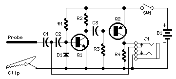
Pulse-Generator & Signal-Tracer
This simple circuit generates narrow pulses at about 700-800Hz frequency. The pulses, containing harmonics up to the MHz region, can be injected into audio or radio-frequency stages of amplifiers, receivers and the like for testing purposes. A high-pitched tone can...

100 transistor circuits
A straightforward method to create a speaker transformer involves winding turns around a ferrite rod. The primary winding consists of 300 turns of 0.01mm wire, which is very fine, wound over the secondary and concluding with a loop of wire...

7555 IC For 5 To 30 Minute Timer
This circuit illustrates the use of the 7555 integrated circuit (IC) for a timer circuit that can be set to operate between 5 to 30 minutes. This circuit is beneficial as it allows for timed operations.
The 7555 timer IC is...

Multi-Zone Transistor-Based Intruder Alarm
This is a simple transistor-based burglar alarm circuit. Its features include automatic exit and entry delays, along with a timed bell cut-off and reset. It is designed to be used with standard types of normally-closed input devices such as magnetic...

Speech compression circuit diagram
An amplifier designed to achieve a voltage gain of approximately 20, utilizing the MPS6517 PNP transistor in the emitter follower configuration. The RI controller allows for adjustment of the transistor's quiescent point. The output signal is activated only when the...

Basic reference bias circuit transistor - negative voltage feedback
Basic reference bias circuit using a transistor with negative voltage feedback.
The basic reference bias circuit utilizing a transistor with negative voltage feedback is designed to provide a stable output voltage or current that is largely independent of variations in temperature...