


External protection signal generator by a circuit diagram TDA4866
#TDA4866
#protection circuit
#signal generator
#pulse generation
#external control
#circuit protection
#timing
#control systems
#electronics

Description: As illustrated in FIG TDA4866, the circuit consists of an external signal generator circuit protection. The internal protection circuit's role is to manage control, while the external protection circuit performs its functions. During normal operation, the vertical amplitude of the output signal is higher, causing the BC556 transistor to turn on. At the same time, the base current of the BC548 transistor is activated, allowing it to function as a low-level output indicator. Conversely, when the circuit is not functioning correctly, the vertical amplitude of the output signal decreases, resulting in the BC556 transistor turning off. In this state, the BC548 transistor receives no base current and also turns off, leading to a high output signal that indicates an error in operation.
The TDA4866 circuit is designed to ensure the integrity and reliability of the signal generation process through its dual-layer protection mechanism. The external signal generator circuit protection serves as a primary defense against potential signal anomalies or external disturbances that may affect the overall operation. The internal protection circuit is tasked with monitoring and controlling the performance of the system, ensuring that any deviations from expected operational parameters are promptly addressed.
The BC556 transistor plays a crucial role in amplifying the output signal during normal conditions. When the vertical amplitude of the output signal is within the acceptable range, the BC556 is activated, allowing for efficient signal amplification. The BC548 transistor, meanwhile, functions as a low-level output indicator, providing a visual or electronic cue to the system's operational status. This transistor is designed to turn on when the base current is sufficient, indicating that the system is functioning as intended.
In scenarios where the circuit encounters issues, the behavior of the transistors changes significantly. A drop in the vertical amplitude of the output signal signifies a malfunction, prompting the BC556 transistor to deactivate. This action is critical as it prevents further amplification of a potentially faulty signal. Simultaneously, the lack of base current to the BC548 transistor causes it to turn off, resulting in a high output signal that serves as an error indication. This dual response mechanism is vital for maintaining the reliability of the circuit and preventing damage due to uncontrolled conditions.
The design of the TDA4866 circuit, with its integrated protection features and transistor-based signaling, exemplifies a robust approach to signal management in electronic systems. The careful interplay between the BC556 and BC548 transistors ensures that the circuit can both amplify and indicate operational status effectively, providing essential feedback for troubleshooting and maintenance. As shown in FIG TDA4866 constituted by an external signal generator circuit protection. The role of the internal protection circuit is out of control, the external protection c ircuit functions. Vertical amplitude of the output signal during normal operation of a larger, BC556 transistor is turned on, while the base current of transistor BC548 get too turned on to work as a low-level output indication. When not working properly, the vertical amplitude of the output signal is low, transistor BC556 is turned off, while transistor BC548 no base current is turned off, the output is high as an error work instructions.
The TDA4866 circuit is designed to ensure the integrity and reliability of the signal generation process through its dual-layer protection mechanism. The external signal generator circuit protection serves as a primary defense against potential signal anomalies or external disturbances that may affect the overall operation. The internal protection circuit is tasked with monitoring and controlling the performance of the system, ensuring that any deviations from expected operational parameters are promptly addressed.
The BC556 transistor plays a crucial role in amplifying the output signal during normal conditions. When the vertical amplitude of the output signal is within the acceptable range, the BC556 is activated, allowing for efficient signal amplification. The BC548 transistor, meanwhile, functions as a low-level output indicator, providing a visual or electronic cue to the system's operational status. This transistor is designed to turn on when the base current is sufficient, indicating that the system is functioning as intended.
In scenarios where the circuit encounters issues, the behavior of the transistors changes significantly. A drop in the vertical amplitude of the output signal signifies a malfunction, prompting the BC556 transistor to deactivate. This action is critical as it prevents further amplification of a potentially faulty signal. Simultaneously, the lack of base current to the BC548 transistor causes it to turn off, resulting in a high output signal that serves as an error indication. This dual response mechanism is vital for maintaining the reliability of the circuit and preventing damage due to uncontrolled conditions.
The design of the TDA4866 circuit, with its integrated protection features and transistor-based signaling, exemplifies a robust approach to signal management in electronic systems. The careful interplay between the BC556 and BC548 transistors ensures that the circuit can both amplify and indicate operational status effectively, providing essential feedback for troubleshooting and maintenance. As shown in FIG TDA4866 constituted by an external signal generator circuit protection. The role of the internal protection circuit is out of control, the external protection c ircuit functions. Vertical amplitude of the output signal during normal operation of a larger, BC556 transistor is turned on, while the base current of transistor BC548 get too turned on to work as a low-level output indication. When not working properly, the vertical amplitude of the output signal is low, transistor BC556 is turned off, while transistor BC548 no base current is turned off, the output is high as an error work instructions.

Test Signal Generator
This signal generator uses a three channel DAC to generate Composite video signal (CVBS) and S video signal (Y/C separated) at the same time, left one channel is not used in NTSC format. It is assigned for one of the...

High and low frequency signal generator circuit diagram
The high-frequency signal generator is designed to produce a low frequency of 1 kHz, an intermediate frequency (IF) signal of 465 kHz, and high frequencies ranging from 525 kHz to 1605 kHz. This device is particularly useful for radio repair...

1kHz signal generator circuit diagram
This circuit can generate a signal of 1 kHz and offers three output level options. It is suitable for testing communication equipment maintenance and barriers, providing a quick and accurate method to identify points of failure in televisions, stereos, radios,...

DIY Homemade Signal Generator with Pulse Width Modulation
Construct a signal generator using readily available components. It should produce a square wave with variable frequency and adjustable pulse width. This device can be utilized for various applications, including DC motor speed regulation, dimming of lamps or LEDs, transformer...
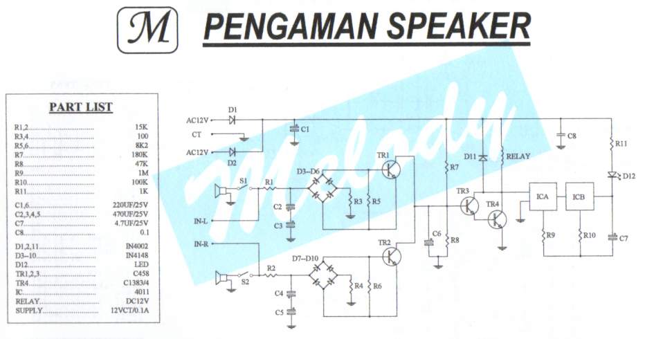
Safety / Protection Circuits
To prevent deep discharge that can damage or shorten the life of a rechargeable battery, it is essential to disconnect its load before the battery is completely discharged. The circuit protects against AC line disturbances by switching off the power...

Signal Generator 20KHz
This function generator IC is specified to work to 20 MHz. So far, this unit works nicely to 50KHz. Since I seldom need signals higher than that, it has taken up a happy home on my workbench and further development...

Timing circuit
Load current starts approximately 0 RC after the switch is thrown.
The statement indicates that the load current begins at approximately 0 ohms after a switch is activated. This scenario is common in electronic circuits where a switch controls the flow...

Signal Generator Circuit
Useful for troubleshooting audio, video, and lower frequency RF amplifiers. This circuit generates a signal that is rich in harmonics.
The circuit designed for troubleshooting audio, video, and lower frequency RF amplifiers is crucial for diagnosing issues in these systems. It...
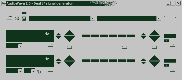
AudioWave 2.0
With AudioWave 2.0 your soundcard becomes a comfortable LF-signal-generator, which produces signals from 1Hz to 20 kHz with a resolution of 1 Hz. Phase shift between left and right channel is adjustable from 180° to +180° and an attenuator can...