


Games Timer Circuit With 4060 And 4017 IC

Description: This is a game timer circuit diagram. When the game timer is reset, two actions must occur: the 4017 counter must return to zero, and the 4060...
The game timer circuit utilizes the 4017 decade counter and the 4060 binary counter to manage timing and sequencing in a gaming application. The 4017 counter is designed to count from 0 to 10, providing a straightforward way to track game intervals or rounds. Upon receiving a reset signal, the 4017 counter is set back to its initial state, effectively restarting the game timer.
The 4060 counter, which operates as a frequency divider, is responsible for generating the clock pulses necessary for timing operations. It can be configured to produce a specific frequency based on external resistor and capacitor values connected to its timing pins. The output from the 4060 can be fed into the clock input of the 4017, ensuring that the counter increments at the desired intervals.
In the schematic, a reset mechanism is typically implemented using a push button switch connected to the reset pins of both counters. When the button is pressed, it sends a low signal to the reset pins, causing both the 4017 and 4060 counters to revert to their initial states. This feature is essential for restarting the timing sequence during gameplay.
Additional components, such as LEDs or display modules, may be integrated into the circuit to provide visual feedback on the current game state or timer status. The overall design should ensure that the power supply is stable, and decoupling capacitors may be included to filter out noise and ensure reliable operation of the counters.
In summary, this game timer circuit diagram showcases a practical application of digital counters to manage timing in gaming scenarios, with a focus on reset functionality and output management for user interaction.This is a games timer circuit diagram. When the games timer is RESET, two things must happen. The 4017 counter must go back to zero and the 4060 ..
The game timer circuit utilizes the 4017 decade counter and the 4060 binary counter to manage timing and sequencing in a gaming application. The 4017 counter is designed to count from 0 to 10, providing a straightforward way to track game intervals or rounds. Upon receiving a reset signal, the 4017 counter is set back to its initial state, effectively restarting the game timer.
The 4060 counter, which operates as a frequency divider, is responsible for generating the clock pulses necessary for timing operations. It can be configured to produce a specific frequency based on external resistor and capacitor values connected to its timing pins. The output from the 4060 can be fed into the clock input of the 4017, ensuring that the counter increments at the desired intervals.
In the schematic, a reset mechanism is typically implemented using a push button switch connected to the reset pins of both counters. When the button is pressed, it sends a low signal to the reset pins, causing both the 4017 and 4060 counters to revert to their initial states. This feature is essential for restarting the timing sequence during gameplay.
Additional components, such as LEDs or display modules, may be integrated into the circuit to provide visual feedback on the current game state or timer status. The overall design should ensure that the power supply is stable, and decoupling capacitors may be included to filter out noise and ensure reliable operation of the counters.
In summary, this game timer circuit diagram showcases a practical application of digital counters to manage timing in gaming scenarios, with a focus on reset functionality and output management for user interaction.This is a games timer circuit diagram. When the games timer is RESET, two things must happen. The 4017 counter must go back to zero and the 4060 ..

Single pulse signal generating circuit
A single pulse signal generating circuit is depicted, which utilizes switch contacts to create a digital signal for reset or stop functions. This one-shot pulse generating circuit operates as a non-synchronous differential circuit.
The single pulse signal generating circuit, commonly referred...

Add-On Pulse Generator Circuit
This pulse generator can enhance a standalone pulse generator. By utilizing a transistor and a 555 timer, it can produce pulse widths ranging from 5 microseconds to 500 microseconds. The value of capacitor C3 can be approximately determined using the...

Camera Switch Circuit using 4017
This circuit functions as a camera switch, allowing multiple cameras to be connected to a single monitor. It can operate in both manual and automatic modes. In automatic mode, the circuit utilizes a 555 astable multivibrator to generate a continuous...
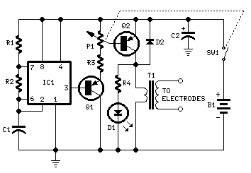
Muscular Bio-Stimulator
IC1 generates 150 µSec pulses at approximately 80Hz frequency. Q1 functions as a buffer, while Q2 inverts the pulse polarity and drives the transformer. The output pulse amplitude is adjusted by P1 and is visually indicated by the brightness of...

Step sequencer
The output of the 4017 has a 100% duty cycle, meaning that if step one and step two are activated, they will overlap, resulting in a step that lasts for two cycles. In contrast, the output of the 555 timer...

Fast Low Duty-Cycle Pulse Oscillator
This simple and symmetrical free-running generator has a 50-ohm output impedance, a pulse width of 100 ns, and complementary outputs that swing from ground to the power supply voltage. It operates within a power supply range of less than 1...
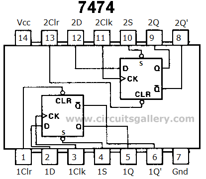
Ring Counter Circuit Working Principle with Animation and Video
Digital counters have various applications in electronic circuits. In digital electronics, counters are utilized in different situations. This article presents the concept of a ring counter circuit, which functions as a register counter. An animation and simulation video of the...

8-bit digital counter circuit
Figure 8 illustrates a potential digital counter circuit. This circuit employs two ICM7217 integrated circuits, with each controlling four digital display tubes.
The digital counter circuit primarily utilizes the ICM7217, a highly integrated chip designed for driving seven-segment displays. Each ICM7217...

1 Hz Generator and 2 Hertz Oscillator Circuit
This 1 Hz and 2 Hz generator or oscillator is constructed using a 4060 IC as the oscillator and a 14-bit counter. To achieve a 1 Hz signal from the 4060, a 1/2 4013 flip-flop is utilized. This circuit generates...