


Line Ripple Clock
#line frequency
#clock
#ripple converter
#wall wart
#digital
#sine wave
#rectifier
#filter
#AC
#frequency

Description: This circuit converts the ripple from a wall wart supply to a clean Line x 2 digital clock. Doing it this way eliminates the need to put AC into the unit, which then has to be rectified and filtered just to have access to the line frequency sine wave.
The described circuit utilizes a wall wart power supply, which typically outputs a DC voltage with some ripple. This ripple is undesirable for precise applications, such as timing circuits found in digital clocks. The primary function of the circuit is to convert this ripple into a stable signal suitable for driving a digital clock that operates at double the line frequency, hence the term "Line x 2."
The circuit likely employs a combination of filtering and signal conditioning techniques to achieve the desired output. Initially, the AC voltage from the wall wart is rectified, possibly using a bridge rectifier configuration. This rectification process converts the AC voltage into a pulsating DC voltage. However, instead of traditional filtering methods that would involve significant components to smooth the output, this circuit may utilize a combination of capacitors and possibly inductors to reduce the ripple effectively.
Following the filtering stage, a voltage regulator may be implemented to ensure that the output voltage remains stable, regardless of variations in the input voltage from the wall wart. This regulator can also provide the necessary isolation from the AC mains, enhancing safety and reducing electromagnetic interference.
To generate the clean line frequency sine wave, the circuit may include a phase-locked loop (PLL) or a microcontroller configured for frequency synthesis. This allows the clock to maintain accurate timekeeping without the need for direct AC input, which simplifies the design and reduces potential points of failure.
Overall, this circuit design is efficient and practical for powering digital clocks, ensuring that the output is not only clean but also reliable, thus eliminating the complexities associated with traditional AC input methods.This circuit converts the ripple from a wall wart supply to a clean Line x 2 digitial clock. Doing it this way eliminates the need to put AC into the unit which then has to be rectified and filtered just to have access to the line frequency sine wave.
The described circuit utilizes a wall wart power supply, which typically outputs a DC voltage with some ripple. This ripple is undesirable for precise applications, such as timing circuits found in digital clocks. The primary function of the circuit is to convert this ripple into a stable signal suitable for driving a digital clock that operates at double the line frequency, hence the term "Line x 2."
The circuit likely employs a combination of filtering and signal conditioning techniques to achieve the desired output. Initially, the AC voltage from the wall wart is rectified, possibly using a bridge rectifier configuration. This rectification process converts the AC voltage into a pulsating DC voltage. However, instead of traditional filtering methods that would involve significant components to smooth the output, this circuit may utilize a combination of capacitors and possibly inductors to reduce the ripple effectively.
Following the filtering stage, a voltage regulator may be implemented to ensure that the output voltage remains stable, regardless of variations in the input voltage from the wall wart. This regulator can also provide the necessary isolation from the AC mains, enhancing safety and reducing electromagnetic interference.
To generate the clean line frequency sine wave, the circuit may include a phase-locked loop (PLL) or a microcontroller configured for frequency synthesis. This allows the clock to maintain accurate timekeeping without the need for direct AC input, which simplifies the design and reduces potential points of failure.
Overall, this circuit design is efficient and practical for powering digital clocks, ensuring that the output is not only clean but also reliable, thus eliminating the complexities associated with traditional AC input methods.This circuit converts the ripple from a wall wart supply to a clean Line x 2 digitial clock. Doing it this way eliminates the need to put AC into the unit which then has to be rectified and filtered just to have access to the line frequency sine wave.

Q-multiplier filter circuit
This circuit is designed for selective tuning adjustments between two closely spaced audio tones. The frequency is determined by the values of the capacitors and resistors in the feedback circuit connecting the collector and base of transistor Q1. With the...

15 V FOR VTVM
A simple rectifier circuit replaces the battery in a vacuum-tube voltmeter (VTVM). It provides good regulation and eliminates the need for frequent battery replacement. The battery should be removed before using the supply. The AC source can be the 6.3-V...

sine wave oscillator
In Japan, the household electricity operates at either 50 Hz or 60 Hz. For a frequency of 50 Hz, one complete sine wave occurs 50 times in one second, while at 60 Hz, it occurs 60 times. Lissajous figures can...

SYNCHRONOUS FILTER FOR ADF
Separates 130-cps motor drive voltage from voice frequencies in the output of an ADF receiver. P. V. Sparks, Servo Filter and Gain Control Improve Automatic Direction Finder, Electronics, 34:23, p 110-113.
The circuit described functions as a filter that effectively separates...

First-order butterworth active Low-pass filter circuit
A Butterworth filter is a type of filter characterized by a frequency response that is flat within the passband region. This filter was first described by British engineer Stephen Butterworth.
A Butterworth filter is designed to provide a maximally flat frequency...

Half wave AC phase-controlled circuit
The 5AH will trigger when the voltage across the two 0 µF capacitors reaches the breakdown voltage of the lamp. Control can be obtained from full off to 95% of the half-wave RMS output voltage. Full power can be achieved...
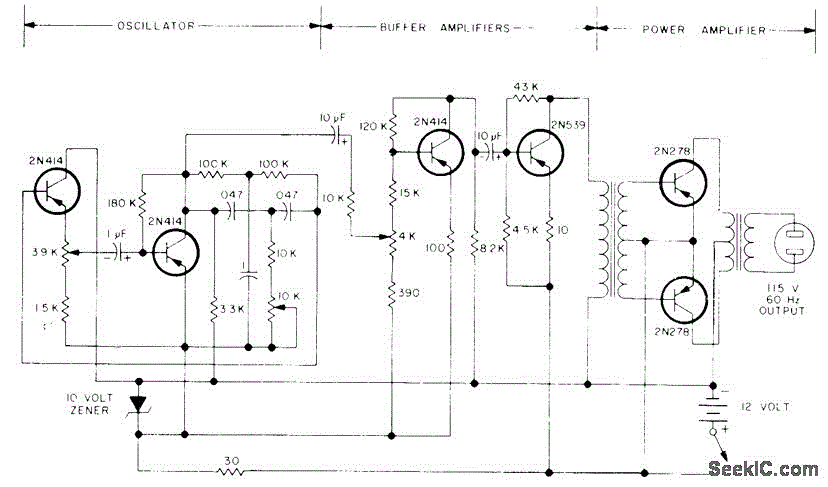
100W SINE AT 60Hz
The circuit primarily comprises a 60-Hz sine-wave oscillator featuring a 10K frequency-control potentiometer, two buffering stages, and a push-pull power amplifier. This design effectively addresses the noise issues associated with square-wave inverters, particularly when powering a 115-V radio receiver or...

Sinewave Oscillator
This circuit generates a 10Hz sine wave using a minimal number of components, based on the specified component values. The active components are generic and can be substituted as needed. The passive component values determine the frequency and should only...

Sine-square wave oscillators
This circuit will provide both a sine and square wave output for frequencies ranging from below 20 Hz to above 20 kHz. The frequency of oscillation can be easily adjusted by changing a single resistor.
This circuit is designed to generate...