


Low-cost-line-receiver
#line receiver
#control applications
#electromechanical
#timer
#low-cost
#pulse
#receiver circuit
#slow devices

Description: This timer serves as an effective line receiver for control applications that involve relatively slow electromechanical devices. It operates without the need for special drivers over single, unshielded lines.
The timer circuit is designed to facilitate communication between control systems and electromechanical devices such as relays and solenoids, which typically require slower response times. Its functionality is particularly beneficial in environments where signal integrity must be maintained over unshielded lines, thus reducing the need for additional components that might complicate the design or increase costs.
The timer can be implemented using a variety of integrated circuits (ICs) that are capable of timing functions. Commonly, a 555 timer IC may be employed in monostable or astable configurations, depending on the specific timing requirements of the application. In a monostable setup, the timer will generate a single output pulse in response to an input trigger, which is ideal for applications requiring a defined delay before activating an electromechanical device. In contrast, an astable configuration allows for continuous oscillation, producing a square wave output that can be useful for generating clock signals or modulating control signals.
The design should include appropriate resistors and capacitors to set the timing intervals, which can be calculated based on the formula provided in the IC's datasheet. Additionally, consideration must be given to the power supply requirements and the input/output voltage levels to ensure compatibility with the connected devices.
For applications that involve longer distances or potential interference, it may be prudent to incorporate filtering or buffering components to enhance signal integrity. Overall, this timer circuit provides a robust solution for control applications involving electromechanical devices, ensuring reliable operation without the complexity of specialized drivers.This timer makes an excellent line receiver for control applications involving relatively slow electromechanical devices. It can work without special drivers over single, unshielded lines.
The timer circuit is designed to facilitate communication between control systems and electromechanical devices such as relays and solenoids, which typically require slower response times. Its functionality is particularly beneficial in environments where signal integrity must be maintained over unshielded lines, thus reducing the need for additional components that might complicate the design or increase costs.
The timer can be implemented using a variety of integrated circuits (ICs) that are capable of timing functions. Commonly, a 555 timer IC may be employed in monostable or astable configurations, depending on the specific timing requirements of the application. In a monostable setup, the timer will generate a single output pulse in response to an input trigger, which is ideal for applications requiring a defined delay before activating an electromechanical device. In contrast, an astable configuration allows for continuous oscillation, producing a square wave output that can be useful for generating clock signals or modulating control signals.
The design should include appropriate resistors and capacitors to set the timing intervals, which can be calculated based on the formula provided in the IC's datasheet. Additionally, consideration must be given to the power supply requirements and the input/output voltage levels to ensure compatibility with the connected devices.
For applications that involve longer distances or potential interference, it may be prudent to incorporate filtering or buffering components to enhance signal integrity. Overall, this timer circuit provides a robust solution for control applications involving electromechanical devices, ensuring reliable operation without the complexity of specialized drivers.This timer makes an excellent line receiver for control applications involving relatively slow electromechanical devices. It can work without special drivers over single, unshielded lines.
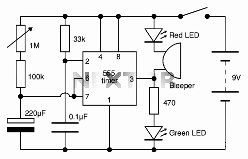
Adjustable Timer circuit 1-10 minute
The Adjustable Timer circuit initiates timing upon activation. A green LED illuminates to indicate that timing is in progress. Once the designated time period elapses, the green LED turns off, the red LED activates, and an audible bleeper sounds. The...

repeating interval timer
This circuit features an adjustable output timer that can re-trigger at regular intervals. The output duration can range from a fraction of a second to over half an hour, with the ability to recur at intervals from seconds to days....

Three Hour Timer
Manufacturers of cordless drills typically recommend a battery charging time of three hours. Once this charging time is complete, the battery must be disconnected from the charger to prevent the risk of overcharging. This circuit, positioned between the charger and...

Timer circuit
After one cycle of operation, SCR1 will be activated, resulting in a low voltage being applied to the UJT emitter circuit, which interrupts the tuning function. When pushbutton SI is pressed, or a positive pulse is applied at point A,...

Up/Down Timer For A Power Antenna
This up/down timer was designed to control a power antenna on a late-model vehicle. Normally, this vehicle uses a body computer to control the antenna. However, the owner intended to install a high-powered audio stereo system. The original stereo system...

Novel circuit diagram of the timer switch
A novel timing switch circuit features a "Variable Timing" adjustment function in addition to a standard timing circuit. It also includes a countdown display feature, which indicates the remaining time of the timing circuit, making it particularly useful. The entire...
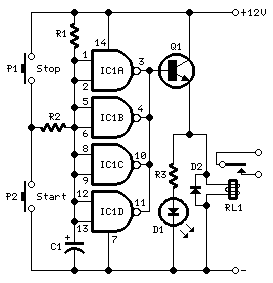
Long Delay TimerCircuit
This timer was designed primarily to switch off a portable radio after a set period. This feature allows users to fall asleep on the beach or in a hammock, knowing that the receiver will automatically turn off after a specified...

A Very Useful Timed Beeper Circuit Schematic
This circuit is designed to provide alerts after a predetermined time interval. It is ideal for tabletop games that necessitate a fixed duration for answering questions or moving pieces. In this context, it serves as a contemporary alternative to the...
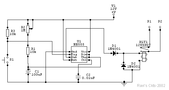
Photo Timer Circuit
The time is set by potentiometer R2, which provides a range from 1 second to 100 seconds, using a timing capacitor C1 of 100 µF. The output at pin 3 is normally low, keeping the relay in the off state.
The...