


Monostable 555 Multivibrator Working Principle and Circuit diagram with Animation
#555 timer
#monostable
#multivibrator
#pulse generator
#RC network
#one shot
#retriggerable
#electronics
#circuit design
#timing circuit

Description: The monostable 555 timer multivibrator circuit, also known as a one-shot monostable multivibrator, functions as a retriggerable pulse generator. The term "monostable" indicates that the circuit has only one stable state, with the unstable state referred to as the "quasi-stable state." The duration of the stable state, or pulse width, is determined by the charging time constant of the RC network. Transitioning the multivibrator from the stable state to the quasi-stable state is achieved using a push-button trigger switch. The operation of the monostable 555 multivibrator can be visualized through simulation. A monostable 555 timer calculator tool is available to easily determine the pulse duration. When the voltage at pin two of the 555 IC drops below 1/3 of the supply voltage (Vcc), the output transitions to a high state, which is considered the quasi-stable state. In this state, the discharge transistor is turned off, allowing the capacitor to charge towards Vcc through resistor R1, with the charging process characterized by the time constant R1C1. As the voltage across the capacitor rises and eventually exceeds 2/3 of Vcc, the internal control flip-flop is reset, turning off the 555 timer IC, as a voltage greater than 2/3 at the threshold pin (pin 6) triggers the reset.
The monostable 555 timer circuit is typically configured with a few essential components: the 555 timer IC, a resistor (R1), a capacitor (C1), and a push-button switch for triggering. The circuit operates in a manner where the capacitor C1 is initially discharged. When the push-button switch is pressed, it momentarily connects pin 2 (the trigger pin) to ground, causing the voltage at this pin to drop below the 1/3 Vcc threshold. This triggers the 555 timer to switch its output (pin 3) to a high state.
The resistor R1 and capacitor C1 together define the timing characteristics of the circuit. The time constant, which dictates how long the output remains high, is calculated using the formula T = 1.1 * R1 * C1. During the pulse duration, the capacitor C1 begins to charge through R1. The charging curve follows an exponential rise, and the output remains high until the voltage across C1 reaches 2/3 Vcc. At this point, the internal flip-flop of the 555 timer is reset, causing the output to return to a low state and the capacitor to begin discharging.
The 555 timer can be retriggered while the output is high; pressing the push-button switch again will restart the timing cycle, which is particularly useful in applications requiring pulse repetition. The circuit can be employed in various applications such as timers, pulse-width modulation, and event counters, illustrating its versatility and effectiveness in generating precise timing signals. The monostable 555 timer circuit is a fundamental building block in electronics, providing reliable and adjustable timing solutions across numerous projects and applications.Monostable 555 timer multivibrator circuit (one shot monostable multivibrator) is a retriggerable mono shot pulse generator. The name Mono stable` indicates that it has only one stable state. The unstable state is called Quasi stable state`. The duration of stable state or the pulse width is determined by the charging time constant of the RC netwo
rk. We can transfer the multivibrator from stable state to quasi stable state by using push button trigger switch. The animated (simulated) working of the mono stable 555 multivibrator is shown in this article. You can use our monostable 555 timer calculator tool to find the duration of pulse(width) easily. As we know, when the voltage at the second pin of 555 IC goes below 1/3 Vcc, the output becomes high.
This high state is known as Quasi stable state`. (Refer Astable multivibrator using NE 555 ) Then the discharge transistor is cut off and capacitor starts charging towards Vcc (Refer the internal circuit below). Charging of capacitor is through the resistor R1 with a time constant R1C1. As the capacitor voltage increases and finally exceeds 2/3 Vcc, it will reset the internal control flip flop, there by turning off the 555 timer IC (more than 2/3 voltage at the threshold pin (6th pin) causes IC to reset).
The monostable 555 timer circuit is typically configured with a few essential components: the 555 timer IC, a resistor (R1), a capacitor (C1), and a push-button switch for triggering. The circuit operates in a manner where the capacitor C1 is initially discharged. When the push-button switch is pressed, it momentarily connects pin 2 (the trigger pin) to ground, causing the voltage at this pin to drop below the 1/3 Vcc threshold. This triggers the 555 timer to switch its output (pin 3) to a high state.
The resistor R1 and capacitor C1 together define the timing characteristics of the circuit. The time constant, which dictates how long the output remains high, is calculated using the formula T = 1.1 * R1 * C1. During the pulse duration, the capacitor C1 begins to charge through R1. The charging curve follows an exponential rise, and the output remains high until the voltage across C1 reaches 2/3 Vcc. At this point, the internal flip-flop of the 555 timer is reset, causing the output to return to a low state and the capacitor to begin discharging.
The 555 timer can be retriggered while the output is high; pressing the push-button switch again will restart the timing cycle, which is particularly useful in applications requiring pulse repetition. The circuit can be employed in various applications such as timers, pulse-width modulation, and event counters, illustrating its versatility and effectiveness in generating precise timing signals. The monostable 555 timer circuit is a fundamental building block in electronics, providing reliable and adjustable timing solutions across numerous projects and applications.Monostable 555 timer multivibrator circuit (one shot monostable multivibrator) is a retriggerable mono shot pulse generator. The name Mono stable` indicates that it has only one stable state. The unstable state is called Quasi stable state`. The duration of stable state or the pulse width is determined by the charging time constant of the RC netwo
rk. We can transfer the multivibrator from stable state to quasi stable state by using push button trigger switch. The animated (simulated) working of the mono stable 555 multivibrator is shown in this article. You can use our monostable 555 timer calculator tool to find the duration of pulse(width) easily. As we know, when the voltage at the second pin of 555 IC goes below 1/3 Vcc, the output becomes high.
This high state is known as Quasi stable state`. (Refer Astable multivibrator using NE 555 ) Then the discharge transistor is cut off and capacitor starts charging towards Vcc (Refer the internal circuit below). Charging of capacitor is through the resistor R1 with a time constant R1C1. As the capacitor voltage increases and finally exceeds 2/3 Vcc, it will reset the internal control flip flop, there by turning off the 555 timer IC (more than 2/3 voltage at the threshold pin (6th pin) causes IC to reset).
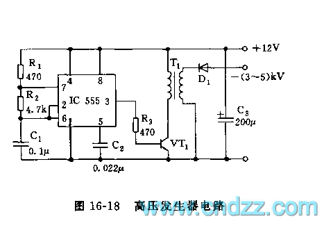
555 high voltage generator circuit
The high voltage generator depicted in figure 16-18 utilizes the 555 timer IC as its primary component. The oscillating voltage produced is enhanced through a step-up transformer. The astable multivibrator configuration comprises the 555 timer along with resistors R1 and...

astable mode of 555 timer
The schematic presented originates from buildcircuit.com. This circuit functions as a music generator, infrared transmitter, and LED blinker, depending on the values of R1, R2, and C1. A minor modification to the previous circuit allows it to operate as an...

Burglar Alarm with 555
This alarm circuit is based on two 555 timers. The alarm will sound your car horn if anyone opens the car door while the circuit is armed. The timers will allow you to leave the car without sounding the horn....

1-20 minutes a timing circuit
The system operates between 10 minutes to 2 hours, featuring a 100-line bell controlled by a multi-gear stick labeled S2 41f. The integrated circuit (IC) functions as a self-excited multivibrator. The device can manage binary pulses ranging from 3 to...

Motor speed controller
During summer nights, the temperature is initially quite high. As time passes, the temperature starts dropping. Also, after a person falls asleep, the metabolic rate of one's body decreases. Thus, initially the fan/cooler needs to be run at full speed....

9V to 5V converter schematic with 555
A 555 timer can be used to generate a square wave to produce a negative voltage relative to the negative battery terminal. When the timer output at pin 3 goes positive, the series 22 uF capacitor charges through the diode...

Digital counter demonstration circuit
The 555 timer is utilized as a clock source to drive the RS7490 decimal counter, providing a BCD output to a 7-segment LED display. The clock frequency can be adjusted by changing the value of resistor R1.
The circuit operates by...

555 LED Flasher Circuit
This is a compact LED flasher circuit designed using the 555 timer integrated circuit (IC), powered by two 1.5V batteries. The circuit can function as a flashing metronome, dark room timer, reminder, or for other similar applications. In the configuration...

555 wailing siren
This tutorial outlines the construction of a wailing siren that produces a tone with varying pitch. The circuit incorporates two 555 integrated circuits (ICs) and a loudspeaker.
The wailing siren circuit is designed to create an audio effect that simulates the...