


Negative-triggered-touch-circuit
#4047
#monostable multivibrator
#negative-triggered
#touch circuit
#one-shot
#timer circuit
#pulse generator
#R1
#C1

Description: The 4047 is configured as a monostable multivibrator circuit, also known as a one-shot, which is triggered by a negative transition of the signal applied to its pin 6 input. The duration of the multivibrator's output pulse is determined by the values of R1 and C1. Although R1 is specified as a 100 kΩ resistor, it can be varied between 10 kΩ and 1 MΩ. Capacitor C1 can be a nonpolarized capacitor with a practical value above 100 pF. By increasing the value of R4 significantly, the circuit can function as a touch-triggered one-shot multivibrator. Conversely, if the value of R4 is reduced to a lower value, such as 10 kΩ, the circuit can be triggered by a negative pulse through a 0.1 µF capacitor connected to pin 6. With a 100 kΩ resistor for R1 and a 4.7 µF electrolytic capacitor for C1, the output pulse duration is approximately 0.6 seconds. Increasing R1 to 470 kΩ extends the output pulse duration to over 6 seconds.
The 4047 monostable multivibrator is an integrated circuit that can be utilized in various applications requiring a single output pulse in response to a triggering event. The circuit is designed to provide a stable output pulse width that can be adjusted by changing the resistor and capacitor values.
The configuration of the circuit includes the following key components:
1. **R1 (Timing Resistor)**: This resistor plays a critical role in determining the output pulse width. The resistance value can be selected based on the desired timing characteristics, with a range from 10 kΩ to 1 MΩ. The typical value used is 100 kΩ, which produces a pulse width of approximately 0.6 seconds when paired with a 4.7 µF capacitor.
2. **C1 (Timing Capacitor)**: The capacitor works in conjunction with R1 to set the timing interval. A nonpolarized capacitor is recommended for use, with values typically above 100 pF. The choice of capacitor value directly influences the duration of the output pulse.
3. **R4 (Trigger Resistor)**: This resistor can be adjusted to modify the sensitivity of the circuit. A high value for R4 allows the circuit to be activated by a simple touch, making it suitable for applications requiring a touch-sensitive interface. Lowering R4 to around 10 kΩ allows the circuit to respond to a negative pulse from an external source, such as a capacitor connected to pin 6.
4. **Trigger Input (Pin 6)**: This pin receives the negative transition signal that triggers the monostable operation. The design allows for flexibility in how the circuit can be activated, either by a touch or by an external pulse.
The output of the 4047 can be connected to various loads or further circuitry, making it a versatile component in timing applications, pulse generation, and event detection systems. The ability to adjust timing parameters by varying resistor and capacitor values provides designers with significant control over the performance of the circuit.The 4047 is configured as a monostable multivibrator circuit or one shot that is set up to trigger on a negative-transition of the signal applied to its pin 6 input. The multivibrator"s on time is determined by the values of R1 and Cl. Although R1 is shown to be a 100-K unit, its value can be anything between 10 K and 1 MO. Capacitor C1 can be a nonpolarized capacitor with any practical value above 100 pF. By making R4"s value extremely high, the circuit can be used as a touch-triggered one-shot multivibrator.
Ifthe value of R4 is reduced to a much lower-value, such as 10 KO, the circuit can be triggered with a negative pulse through 0.11-" F capacitor connected to pin 6. With a 100-KO resistor for R1, and a 4. 7-flF electrolytic capacitor for C1, the circuit"s on time is about 0.6 second. When R1 is increased to 4 70 KO, the on time of the circuit is increased to over 6 seconds.
The 4047 monostable multivibrator is an integrated circuit that can be utilized in various applications requiring a single output pulse in response to a triggering event. The circuit is designed to provide a stable output pulse width that can be adjusted by changing the resistor and capacitor values.
The configuration of the circuit includes the following key components:
1. **R1 (Timing Resistor)**: This resistor plays a critical role in determining the output pulse width. The resistance value can be selected based on the desired timing characteristics, with a range from 10 kΩ to 1 MΩ. The typical value used is 100 kΩ, which produces a pulse width of approximately 0.6 seconds when paired with a 4.7 µF capacitor.
2. **C1 (Timing Capacitor)**: The capacitor works in conjunction with R1 to set the timing interval. A nonpolarized capacitor is recommended for use, with values typically above 100 pF. The choice of capacitor value directly influences the duration of the output pulse.
3. **R4 (Trigger Resistor)**: This resistor can be adjusted to modify the sensitivity of the circuit. A high value for R4 allows the circuit to be activated by a simple touch, making it suitable for applications requiring a touch-sensitive interface. Lowering R4 to around 10 kΩ allows the circuit to respond to a negative pulse from an external source, such as a capacitor connected to pin 6.
4. **Trigger Input (Pin 6)**: This pin receives the negative transition signal that triggers the monostable operation. The design allows for flexibility in how the circuit can be activated, either by a touch or by an external pulse.
The output of the 4047 can be connected to various loads or further circuitry, making it a versatile component in timing applications, pulse generation, and event detection systems. The ability to adjust timing parameters by varying resistor and capacitor values provides designers with significant control over the performance of the circuit.The 4047 is configured as a monostable multivibrator circuit or one shot that is set up to trigger on a negative-transition of the signal applied to its pin 6 input. The multivibrator"s on time is determined by the values of R1 and Cl. Although R1 is shown to be a 100-K unit, its value can be anything between 10 K and 1 MO. Capacitor C1 can be a nonpolarized capacitor with any practical value above 100 pF. By making R4"s value extremely high, the circuit can be used as a touch-triggered one-shot multivibrator.
Ifthe value of R4 is reduced to a much lower-value, such as 10 KO, the circuit can be triggered with a negative pulse through 0.11-" F capacitor connected to pin 6. With a 100-KO resistor for R1, and a 4. 7-flF electrolytic capacitor for C1, the circuit"s on time is about 0.6 second. When R1 is increased to 4 70 KO, the on time of the circuit is increased to over 6 seconds.
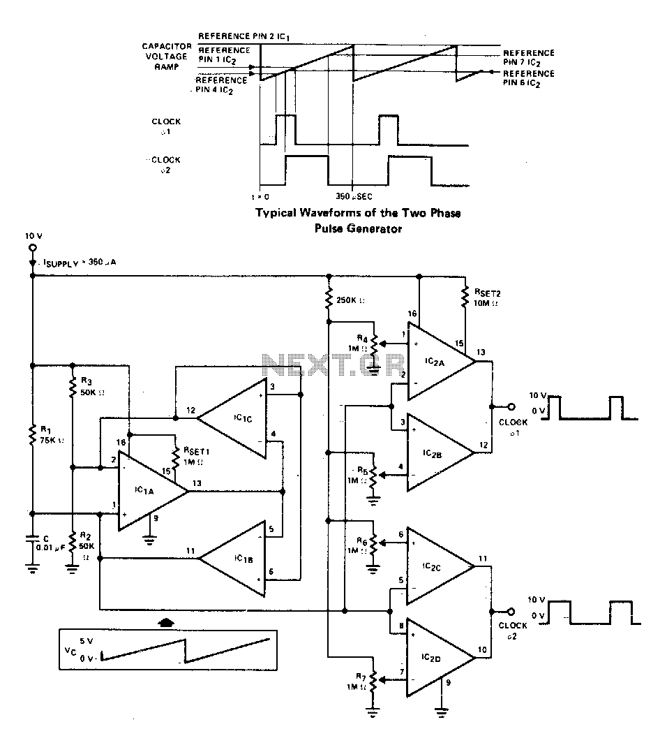
Versatile two-phase pulse generator
A two-phase clock generator utilizes two L161 integrated circuits to produce pulses with adjustable widths and phase relationships. Additionally, a ramp generator supplies input to two variable window comparators, which are configured using IC2A-IC2B and IC2C-IC2D, respectively.
The two-phase clock generator...
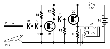
Pulse-Generator & Signal-Tracer
This simple circuit generates narrow pulses at about 700-800Hz frequency. The pulses, containing harmonics up to the MHz region, can be injected into audio or radio-frequency stages of amplifiers, receivers and the like for testing purposes. A high-pitched tone can...

2Hz unsteady pulse single circuit diagram
The duty cycle of the capacitive circuit is very low, ranging from 1% to 10%. When the current is only 50 mA, the battery current consumption is just 1 A. Resistor R4 and capacitor C control the opening time, while...
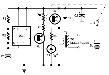
Muscular Bio-Stimulator
IC1 generates 150 µSec pulses at approximately 80Hz frequency. Q1 functions as a buffer, while Q2 inverts the pulse polarity and drives the transformer. The output pulse amplitude is adjusted by P1 and is visually indicated by the brightness of...

PULSE DELAY
When a GATE signal (between 3V and 15V) is applied, the capacitor C5 functions as a differentiator, converting the gate signal into a brief positive pulse with a width of 10 ms. Diode D1 protects the circuit from negative voltages....

Adjustable pulse generator circuit
An adjustable pulse generator circuit is presented, which produces a periodic signal with independently adjustable pulse widths. The electrical path allows for modifications to the signal period through the adjustment of RP1. Additionally, RP2 can be altered to change the...

Pulse Generator Oscillator 32.768KHz by watch crystal
A friend requires a pulse generator oscillator circuit that maintains a stable frequency of 32.768 kHz for a digital CMOS binary counter.
The pulse generator oscillator circuit designed to operate at a frequency of 32.768 kHz is commonly used in digital...

Electronic circuitry Dot Award
Dot Award. This circuit is tested and functional. The circuit consists of two integrated circuits (ICs). IC1 serves as a pulse source, activated by a momentary button switch (S). When the button is pressed, it charges capacitor C1, which powers...

Versatile One-Shot Cpu Interface
Process control applications often require a monostable multivibrator (one-shot) with a pulse width that can be selected on-the-fly. This circuit uses two CD4051B analog multiplexers to select the required timing components for the multivibrator, and hence, the pulse width. The...