


One-shot-timer

Description: This simple circuit consists of only two timing components, Rr and Cr, the NE555 timer, and a bypass capacitor C2. Although C2 is not essential for operation, it is recommended for noise immunity. During standby, the trigger input terminal is held above 1/3 Vee, resulting in a low output. When a trigger pulse appears with a level below 1/3 Vcc, the timer is activated, initiating the timing cycle. The output then rises to a high level near Vcc, while Cr begins to charge towards Vcc. When the voltage across Cr exceeds 2/3 Vcc, the timing period concludes, and the output drops to zero, preparing the circuit for another input trigger. Due to the internal latching mechanism, the timer will always time out when triggered, regardless of any subsequent noise, such as bounce, on the trigger input. Consequently, the circuit can also function as a bounceless switch by employing a shorter RC time constant. A 100 kΩ resistor for Rr and a 1 µF capacitor for Cr would produce a clean 0.1-second output pulse when used as a bounceless switch.
This circuit utilizes the NE555 timer in monostable mode, where the timing components Rr (the resistor) and Cr (the capacitor) define the duration of the output pulse. The NE555 timer is a versatile and widely used integrated circuit that can generate precise timing and oscillation. In this configuration, the circuit remains in a stable low state until triggered by an input pulse.
The bypass capacitor C2, while not critical for the basic functionality of the circuit, plays a significant role in enhancing performance by filtering out high-frequency noise that could affect the operation of the timer. It is typically connected between the power supply pin and ground, ensuring stable voltage levels during operation.
The operation begins when the trigger input receives a pulse that momentarily drops below 1/3 of the supply voltage (Vcc). This causes the internal flip-flop of the NE555 to change state, driving the output high. The charging of Cr through Rr determines the length of time the output remains high. The time period (T) can be calculated using the formula T = 1.1 * Rr * Cr, where T is in seconds, Rr is in ohms, and Cr is in farads.
Once the voltage across Cr reaches 2/3 Vcc, the NE555 resets its output to low, completing the timing cycle. The internal mechanism ensures that any noise spikes or bouncing on the trigger line do not inadvertently retrigger the timer, making this circuit suitable for applications requiring reliable triggering, such as in switch debounce applications.
For bounceless switching, selecting Rr as 100 kΩ and Cr as 1 µF results in a timing duration of approximately 0.1 seconds, allowing for quick response times in applications such as push-button switches. This configuration effectively isolates the switch from noise, providing clean and reliable output signals.This simple circuit consists of only two timing components Rr and Cr, the NE555, and bypass capacitor C2. While not essentiaHor operation, C2 is recommended for noise immunity. During standby, the trigger input terminal is held higher than 1/3 Vee and the output is low. When a trigger pulse appears with a level less than 1/3 Vce, the timer is triggered and the timing cycle starts.
The output rises to a high level near Vcc. and at the same time, Crbegins to charge toward Vc·e· When the Crvoltage crosses 2 /3 Vco the timing period ends with the output falling to zero, and the circuit is ready for another input trigger. Because of the internal latching mechanism, the timer will always time out when triggered, regardless of any subsequent noise, such as bounce, on the trigger input.
For this reason, the circuit can also be used as a bounceless switch by using a shorter rc time constant. A 100-KO resistor for Rrand a 1-f."F capacitor for Cr would give a clean, 0.1 s output pulse when used as a bounceless switch.
This circuit utilizes the NE555 timer in monostable mode, where the timing components Rr (the resistor) and Cr (the capacitor) define the duration of the output pulse. The NE555 timer is a versatile and widely used integrated circuit that can generate precise timing and oscillation. In this configuration, the circuit remains in a stable low state until triggered by an input pulse.
The bypass capacitor C2, while not critical for the basic functionality of the circuit, plays a significant role in enhancing performance by filtering out high-frequency noise that could affect the operation of the timer. It is typically connected between the power supply pin and ground, ensuring stable voltage levels during operation.
The operation begins when the trigger input receives a pulse that momentarily drops below 1/3 of the supply voltage (Vcc). This causes the internal flip-flop of the NE555 to change state, driving the output high. The charging of Cr through Rr determines the length of time the output remains high. The time period (T) can be calculated using the formula T = 1.1 * Rr * Cr, where T is in seconds, Rr is in ohms, and Cr is in farads.
Once the voltage across Cr reaches 2/3 Vcc, the NE555 resets its output to low, completing the timing cycle. The internal mechanism ensures that any noise spikes or bouncing on the trigger line do not inadvertently retrigger the timer, making this circuit suitable for applications requiring reliable triggering, such as in switch debounce applications.
For bounceless switching, selecting Rr as 100 kΩ and Cr as 1 µF results in a timing duration of approximately 0.1 seconds, allowing for quick response times in applications such as push-button switches. This configuration effectively isolates the switch from noise, providing clean and reliable output signals.This simple circuit consists of only two timing components Rr and Cr, the NE555, and bypass capacitor C2. While not essentiaHor operation, C2 is recommended for noise immunity. During standby, the trigger input terminal is held higher than 1/3 Vee and the output is low. When a trigger pulse appears with a level less than 1/3 Vce, the timer is triggered and the timing cycle starts.
The output rises to a high level near Vcc. and at the same time, Crbegins to charge toward Vc·e· When the Crvoltage crosses 2 /3 Vco the timing period ends with the output falling to zero, and the circuit is ready for another input trigger. Because of the internal latching mechanism, the timer will always time out when triggered, regardless of any subsequent noise, such as bounce, on the trigger input.
For this reason, the circuit can also be used as a bounceless switch by using a shorter rc time constant. A 100-KO resistor for Rrand a 1-f."F capacitor for Cr would give a clean, 0.1 s output pulse when used as a bounceless switch.

A welding load automatic power-off circuit
The NE555 timer circuit functions as a vibration generator. The input pin 3 produces pulse frequencies ranging from 5 to 20 Hz. The circuit includes a fan that operates within a bamboo enclosure. The barrel section is designed to accommodate...

Extended On Time Timer Circuit
Half of a Motorola MG14538B dual precision retriggerable monostable multivibrator is utilized to create an extended on-time timer circuit. This type of circuit can function as a switch debouncer. Such circuits are commonly implemented in digital applications, where every bounce...

Digital Stop Watch and Digital Timer Circuit
A digital stopwatch or digital timer circuit schematic is constructed using the timer IC LM555 and the 4-digit counter IC MM74C926, which is paired with a multiplexed 7-segment LED display.
The digital stopwatch circuit utilizes the LM555 timer IC configured in...

Discharge time relay circuit
Discharge time relay circuit. The timer utilizes a field effect transistor, providing high timing accuracy and extended timing capabilities. With R3 set to 1,000,000 ohms and C at 200 microfarads, a delay time of 8 hours can be achieved. When...
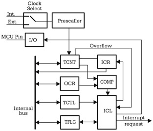
Using the MCU Timers
Although there are significant variations between different implementations of the general-purpose timer in various microcontrollers, many similarities exist in the principles of operation and the structure of the timer subsystem. The central element of the timer subsystem is a counter,...

R/C Timer-Switch for Radio Control Applications
The project originated from a request by Tony Bowler, a member of the Long Eaton Club, who sought assistance in converting a "Golden Oldie" model to electric free-flight. He selected Vic Smeed's "Debutante" to be powered by seven AE size...

NE555 Astable Multivibrator Frequency and Duty Cycle Calculator
This calculator computes the resistor and capacitor values for a NE555 timer chip configured as an astable multivibrator (oscillator) or square wave generator. By entering the desired duty cycle and frequency, the calculator provides suitable values for the resistors and...

DC to DC Converter 6
This circuit utilizes the NE555 integrated circuit configured as a stable multivibrator. It generates a rectangular wave frequency of approximately 100 Hz, outputting from pin 3 through capacitors C3 and C4, preceding the rectifier power section. The circuit employs both...

The switch shut off time delay circuit diagram
The switch shut-off time delay circuit consists of a timer, optocouplers, a bridge SCR, and an SCR AC switch. When the control button is released, it allows the motor or other AC power to remain active for one hour. Upon...