


Pulse width / voltage conversion circuit composed of TL082
#TL082
#pulse width
#voltage conversion
#analog switch
#integrator
#signal processing
#operational amplifier
#time measurement
#circuit design
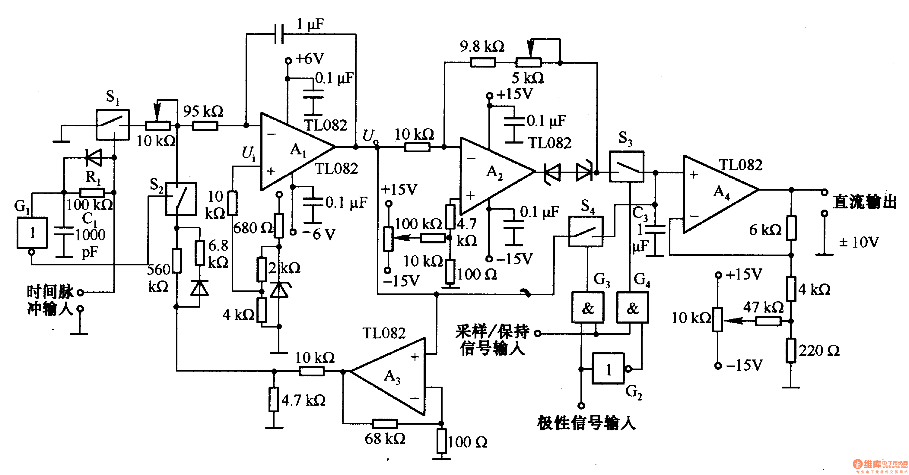
Description: This circuit is designed for pulse width (time) to voltage conversion. According to the component parameters in the diagram, it can convert a pulse width of 0.1 seconds into an output voltage of 10V. When a conversion pulse is applied to the input, the analog switch S1 is disconnected while S2 is connected, resulting in the output of the integrator A1 being 0V. This state is maintained until the input pulse is increased. Once the pulse is added, S1 is activated, and S2 is turned off, cutting off the feedback loop. Consequently, integrator A1 begins to integrate the reference voltage, causing its output to decrease in the negative direction and transition to a low level at the end of the integration. If the input pulse returns to a low state, S1 is immediately disconnected.
The pulse width to voltage conversion circuit operates on the principle of integrating a reference voltage over a specified time interval defined by the input pulse width. The core component of this circuit is the operational amplifier configured as an integrator (A1). The integration process begins when the input pulse is detected, which activates the appropriate switches (S1 and S2) to control the feedback loop.
Initially, when a pulse width of 0.1 seconds is applied, S1 is opened, and S2 is closed, resulting in an output of 0V from the integrator. This state is stable until the input pulse is increased. Once a new pulse is detected, S1 closes, allowing the feedback loop to engage while S2 opens. The integrator then starts to accumulate the reference voltage, which is typically set to a predetermined value that will yield the desired output voltage of 10V after the integration period.
As the integrator processes the input pulse, the output voltage decreases in the negative direction due to the nature of the integration operation. The output will reach a low level once the integration period concludes, indicating that the pulse width has been fully processed. If the input pulse subsequently drops to a low state, S1 is immediately opened, halting the integration process and returning the circuit to its initial state.
This circuit is particularly useful in applications where precise voltage control based on pulse width modulation is required, such as in motor speed control, signal processing, or in digital-to-analog conversion systems. The careful selection of component values, including the resistors and capacitors associated with the integrator, will directly influence the accuracy and responsiveness of the output voltage to changes in pulse width.This is the pulse width (time) / voltage conversion circuit, according to the diagram component parameters, it can convert 0. 1 S pulse width into 10V output voltage. When time pulse input end is added input conversion pulse, the analog switch Sl is disconnected, and S2 is connected, then Al integrator output is OV.
This state has been maintained t o be increased the input pulse. After added pulse, Sl is turned on and S2 is off, and the feedback loop is cut off, then Al makes integral on the reference voltage, and its output reduces in the negative direction and changes into low level at the end of integral. If the input pulse goes low, Sl is immediately disconnected.
The pulse width to voltage conversion circuit operates on the principle of integrating a reference voltage over a specified time interval defined by the input pulse width. The core component of this circuit is the operational amplifier configured as an integrator (A1). The integration process begins when the input pulse is detected, which activates the appropriate switches (S1 and S2) to control the feedback loop.
Initially, when a pulse width of 0.1 seconds is applied, S1 is opened, and S2 is closed, resulting in an output of 0V from the integrator. This state is stable until the input pulse is increased. Once a new pulse is detected, S1 closes, allowing the feedback loop to engage while S2 opens. The integrator then starts to accumulate the reference voltage, which is typically set to a predetermined value that will yield the desired output voltage of 10V after the integration period.
As the integrator processes the input pulse, the output voltage decreases in the negative direction due to the nature of the integration operation. The output will reach a low level once the integration period concludes, indicating that the pulse width has been fully processed. If the input pulse subsequently drops to a low state, S1 is immediately opened, halting the integration process and returning the circuit to its initial state.
This circuit is particularly useful in applications where precise voltage control based on pulse width modulation is required, such as in motor speed control, signal processing, or in digital-to-analog conversion systems. The careful selection of component values, including the resistors and capacitors associated with the integrator, will directly influence the accuracy and responsiveness of the output voltage to changes in pulse width.This is the pulse width (time) / voltage conversion circuit, according to the diagram component parameters, it can convert 0. 1 S pulse width into 10V output voltage. When time pulse input end is added input conversion pulse, the analog switch Sl is disconnected, and S2 is connected, then Al integrator output is OV.
This state has been maintained t o be increased the input pulse. After added pulse, Sl is turned on and S2 is off, and the feedback loop is cut off, then Al makes integral on the reference voltage, and its output reduces in the negative direction and changes into low level at the end of integral. If the input pulse goes low, Sl is immediately disconnected.

Analog switches carrier suppression amplitude modulation circuit
An analog switch (double loop, double-break) and a differential modulation amplifier are used in this circuit. The carrier control switch operates by switching contacts at specific times, inverting the input modulation wave. When the next carrier signal is applied to...

Square transform circuit diagram
At the input of the operational amplifier, a resistor-diode network can be constructed to create a square-law function conversion circuit. This resistor-diode network acts as a voltage divider, where the input voltage variations lead to different partial pressures. The three...

Opamp Wien-bridge oscillator
The Wien-bridge oscillator consists of an operational amplifier (OA) in a non-inverting configuration with a gain of 1 + R2/R1 and an RC feedback network.
The Wien-bridge oscillator is a type of electronic oscillator that generates sine waves. It employs a...

Precision current sink sourcel
An operational amplifier circuit can provide a constant voltage source with a high amplification factor and substantial load current. Even with significant variations in circuit parameters, the output voltage maintains high precision. The output current limit is managed by transistors...

Long timed circuit diagram LM307N CA3094
The long timer circuit utilizes an operational amplifier, specifically the CA3094, to control the discharge formula for extended timing. This is typically achieved by adjusting the variable resistor RV1, which alters the timing duration to meet specific requirements.
The long timer...

GF2A op amp audio amplifier circuit diagram
The operational amplifier A is utilized in an audio preamplifier circuit. Its advantages include compact size, low noise, low power consumption, and excellent consistency. The operational amplifier can achieve significant negative feedback while increasing output without distortion. The signal distortion...

Analog Line Switch Circuit
This analog switch circuit is designed to switch an analog line on or off. It consists of two analog switches in integrated circuit (IC) form that are controlled by two pushbuttons.
The described analog switch circuit utilizes two integrated analog switches...

SIMPLE TLO82 VCO
This circuit utilizes a dual operational amplifier (TL082) to create a voltage-controlled oscillator (VCO). The specified component values allow the output frequency to range from 100 Hz to 10 kHz when the input control voltage varies between 0.05 V and...

Interpolating Scanner Circuit
This design is for an interpolating scanner, a circuit featuring multiple signal inputs, a control voltage input, and a signal output. The output selectively transitions between inputs, smoothly fading from one to the next as the control voltage increases. A...